53
GB
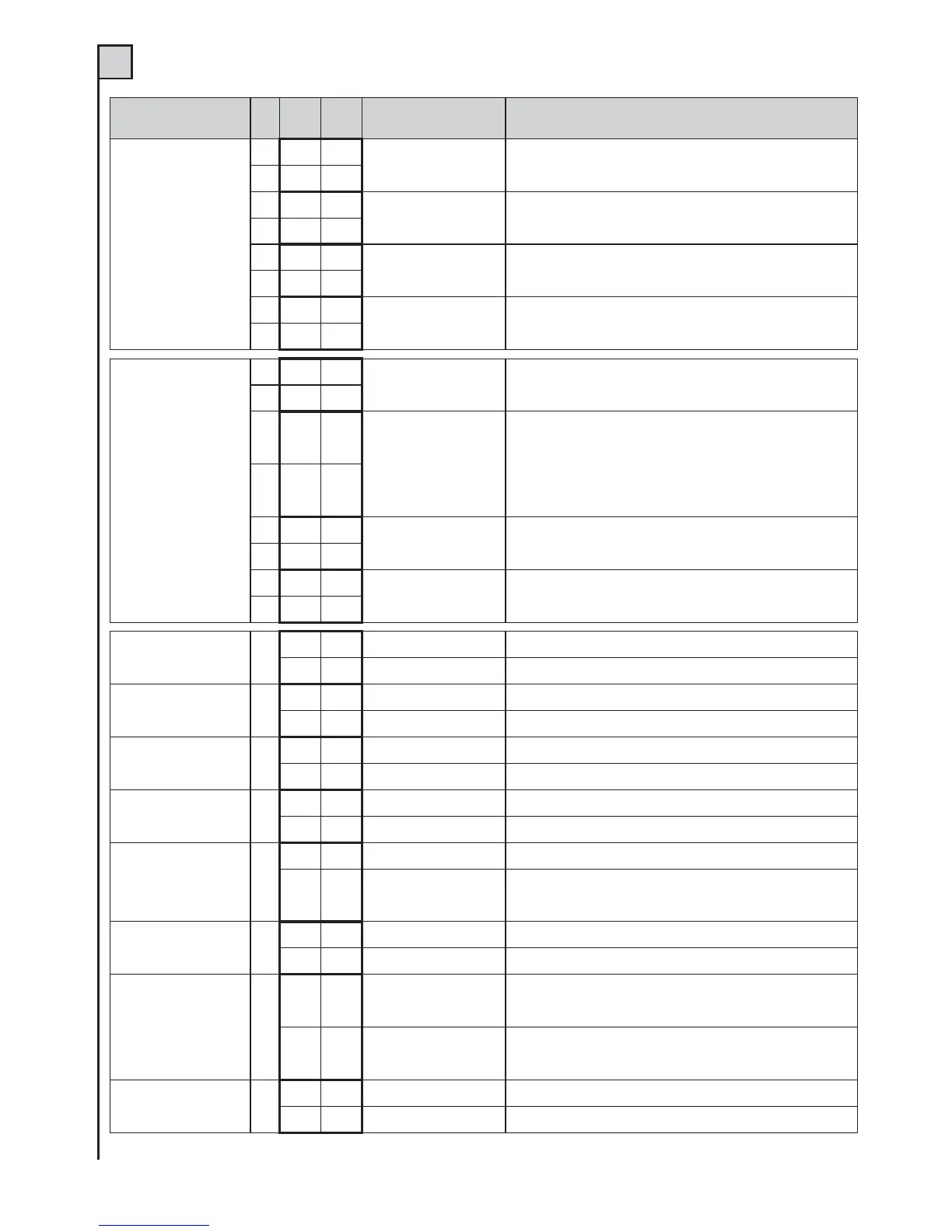
Function
N.
Dip
OFF ON
Desciption Notes
Step-by-step
input and radio
channel mode
1
•
Open - Stop - Close
During opening, upon pressing the P/P button the gate stops, pressing it
again the gate closes. During closing, upon pressing the P/P button the
gate stops, pressing it again the gate opens.
2
•
1
•
Open - Close
During opening, upon pressing the P/P button the gate stops for a few
seconds and then closes. During closing, upon pressing the P/P button
the gate stops for a few seconds and then opens.
2
•
1
•
Open
Condominium function
During opening, pressing the P/P button has no effect. During the pause,
pressing the P/P button has no effect. During closing, upon pressing the
P/P button the gate stops for a few seconds and then opens.
2
•
1
•
Open - Close
Cut out of opening control
During opening, pressing the P/P button has no effect. During the pause,
upon pressing the P/P button the gate closes. During closing, upon pressing
the P/P button the gate stops for a few seconds and then opens.
2
•
Jolly input mode
3
•
J1=Open pushbutton
J2=Close pushbutton
J1 = opening pushbutton
J2 = closing pushbutton
Use NO contacts or pushbuttons
4
•
3
•
J1=Opening Edge
J2=Photocell 3
J1 = “opening edge” input. This safety device is triggered only when the
gate is opening. The fixed edge (terminal 27) becomes “closing edge”,
so it is activated during the closing of the gate. These two safety devices
reverse the moving direction of the gate for a short time.
J2 = input for third photocell; it activates only during an opening manoeuvre
and causes the gate to close. Use N.C. contact.
4
•
3
•
2nd pair of limit switches
J1=FCA J2=FCC
For installations where 4 limit switches (gate stops) are mounted. Connect
the motor M1 limit switches to the inputs FCC and FCA. Connect the
motor M2 limit switches to the inputs J1 and J2. Use NC contacts.
4
•
3
•
J1=Clock
J2=Photocell 3
J1=Clock input; this closes the gate when the contact is opened and
opens it when the contact is closed. J2=input for the third photocell; it only
activates during opening and forces closing. Use NC contacts.
4
•
Pre-flashing light 5
•
Cut out
The flashing light is powered at the same time as the motor.
•
Connected
The flashing light is powered 5 seconds before any movement.
Re-closure 6
•
Cut out
After one complete opening, the control unit only closes again witha manual control.
•
Connected
After one complete opening, the control unit closes automaticallyafter the
programmed pause time.
Photo test 7
•
Cut out
See text in Fototest section.
•
Connected
See text in Fototest section.
Release thrust 8
•
Cut out
Function cut out.
•
Connected
The release thrust has the function of releasing the electric lock. The leaf
with M1gives a short thrust in the closing direction before starting to open.
Slowdown 9
•
Cut out
There is no slowdown in the last part of travel.
•
Connected
With the slowdown function connected, the motor halves its speedtowards
the end of every gate movement. This function may not workproperly with
hydraulic motors.
Closing thrust 10
•
Cut out
No closing thrust is carried out.
•
Connected
The control unit ends gate closure with a short full-power thrust onmotor M1.
Mode 11
•
Control unit for 1
motor or 2 in parallel
The outputs M1 and M2 work in parallel and the pedestrian control
partially opens/closes the gate leaf/s. For single motor control, see the
section “Programming the times”.
•
Control unit for 2
independent motors
The outputs M1 and M2 are independent and the pedestrian control
fully opens and closes the leaf with motor M1. For motor control, see the
section “Programming the times”.
Reclosing after the
photoelectric cells
12
•
Cut out
Function bypassed
•
Connected
The activation of photoelectric cell reduces the pause time for whatever is
value previously was to 2 seconds.
TAB. 2 (det. 14 of fig. 1)
 Loading...