52
GB
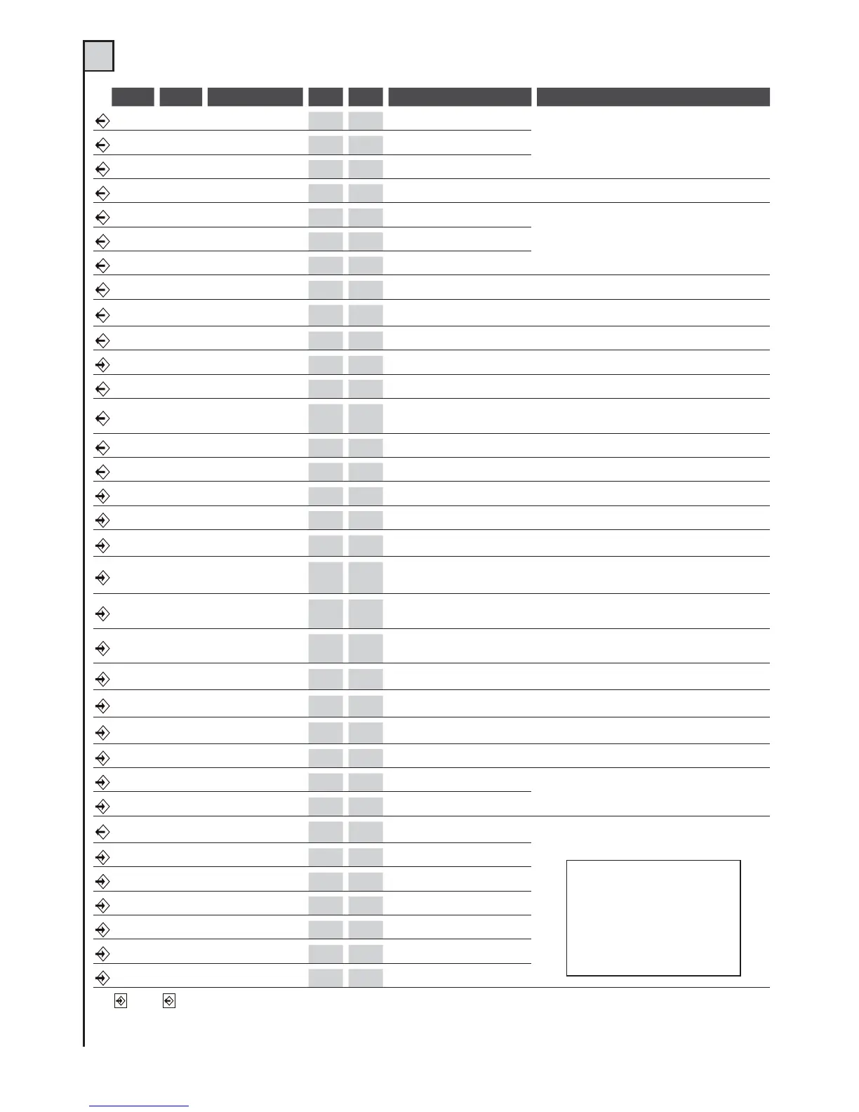
TAB. 1 (see fig. 2)
Mor n. Mor n. Device V I max Function Notes
1 Motor M1
230Vac 4A
Common M1
The motor M1 is delayed for gate clo-sing.
In swing gate installations the motor M1 should
control theleaf with the electric lock.
2 Motor M1
230Vac 4A
Close M1
3 Motor M1
230Vac 4A
Open M1
23Capacitor
230Vac 4A
Motor breakaway M1
See motor notes
4 Motor M2
230Vac 4A
Common M2
The motor M2 is delayed for gateopening (with dip-
switch n. 11 set to ON)
5 Motor M2
230Vac 4A
Close M2
6 Motor M2
230Vac 4A
Open M2
56Capacitor
230Vac 4A
Motor breakaway M2
See motor notes
78Flashing light
230Vac 1A
Movement indicator
On when the motor is working. Switchingon may be
anticipated (pre-blinking), seedipswitch No.5 functions
98Light
230Vac 1A
Courtesy light
On, from start of movement to 3minutes after full closure
10 11 Line
230Vac 6,3A
C. unit power supply
Connect to the 230Vac line. See”ELECTRICAL CONNECTIONS”
12 13 Auxiliares
24Vac 150mA
Power supply
Permanent for photocells and auxiliaries power supply
14 15
Photocell/s
transmitter
24Vac 150mA
Transmitter power supply
for foto-test
Power supply for photocell transmitter (if the Foto test
function is used)
15 16 Warning light
24Vac 100mA
Gate open
Use a 24V 2W max. bulb, see text
17 18 Electric lock
12Vcc 1A
Mechanical lock
Active for a few seconds at everystart of opening
20 19 o 25 N.C. contact Closing limit switch (M1)
Connect this input if not used to thecommon terminal.
21 19 o 25 N.C. contact Opening limit switch (M1)
Connect this input if not used to thecommon terminal.
22 19 o 25 N.C. contact Photocell 1
During closure it reverses the direc-tion.
Connect this input if not used tothe common terminal
23 19 o 25 N.C. contact Photocell 2
Temporary stop during opening. During clo-sing
it reverses the direction. Connect thisinput to the
common terminal if it is notused.
24 19 o 25
N.C. contact or
N.O. pushbutton
Jolly 2
See dipswitch No.3 and 4 functions.
If this input is not used, put dipswitches 3 and 4 to OFF.
26 25 o 31
N.C. contact or
N.O. pushbutton
Jolly 1
See dipswitch No.3 and 4 functions.
If this input is not used, put dipswitches 3 and 4 to OFF.
27 25 o 31 N.C. contact Fixed safety edge
Reverse the direction for a few seconds and the control unit
locks. Connect this input tothe common terminal if it is not used.
28 25 o 31
N.O. pushbutton
Pedestrian gate
With 2 motors, opening is carried outby just motor
M1. With 1 motor, opening is for just 6 seconds.
29 25 o 31 N.C. contact Stop
Stop all functions. Connect this input ifnot used to the
common terminal.
30 25 o 31
N.O. pushbutton
Step-by-step
See functions dipswitches No.1 and No.2
32
Receiver antenna Rx*
Control unit
Connect an aerial suited to the receiver model
33
Receiver antenna Rx*
Braid
34 35 Auxiliares
Max 24V
500mA
II° Receiver channel
Only available if a two-channel radiocard is inserted
in the pre-installed connector (det. 13 of fig. 1).
36 Encoder 2
0 V
Negative power supply
See motor instructions
37 Encoder 2
~20V
Positive power supply
38 Encoder 2 Data
39 Encoder 1
0 V
Negative power supply
40 Encoder 1
~20V
Positive power supply
41 Encoder 1 Data
Input Output
*ANTENNA: pay attention if a plug-in radio card is used, since the connector for antenna connection in certain models
is on the actual card.
 Loading...