Page 2 Telecor Administrative Communication Systems
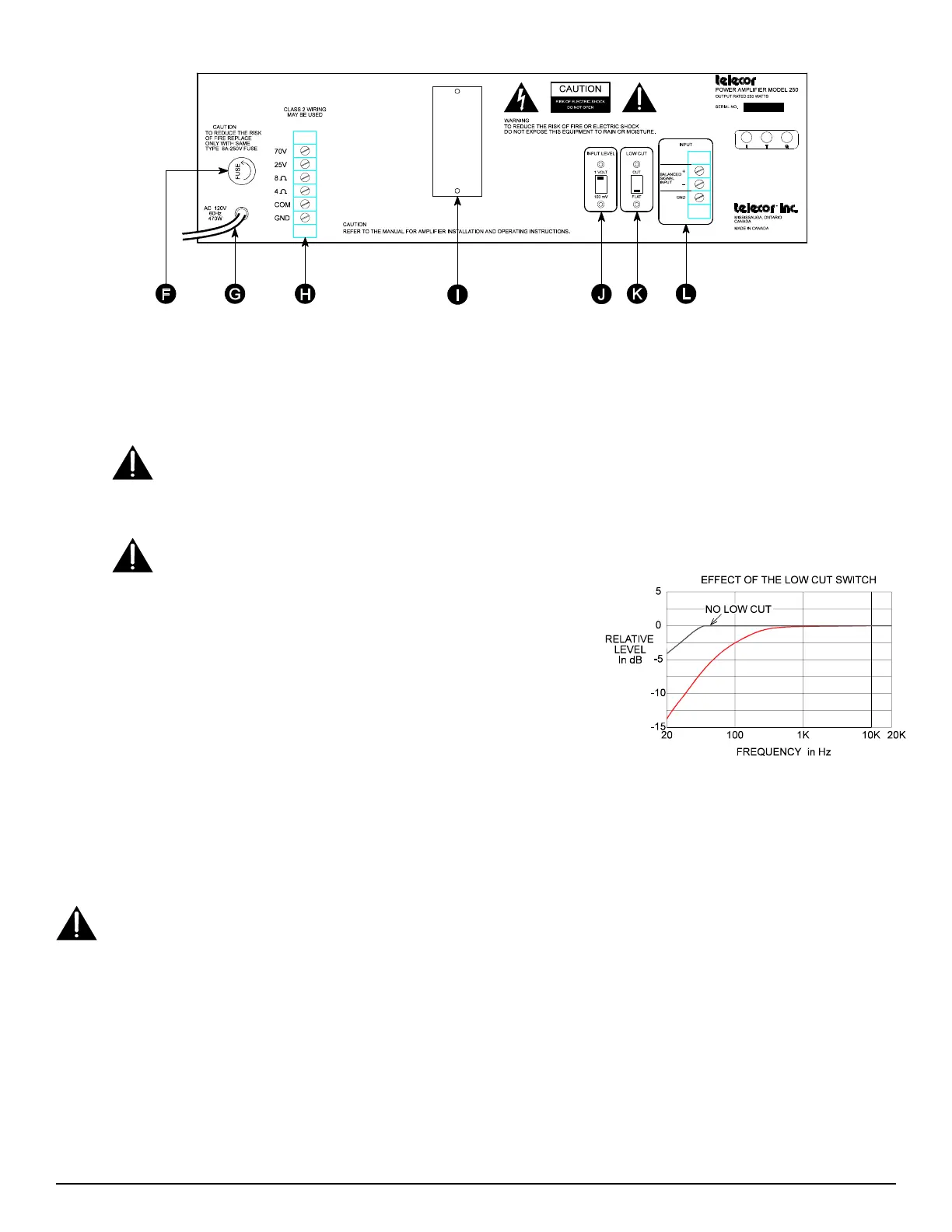
Figure 2: Rear View of Power Amplifier
F FUSE:
Protects the amplifier if the maximum current draw is exceeded. If the fuse blows, see the section on Troubleshooting.
G AC Power Cord:
Connects the amplifier to a standard 120 V, 60 Hz grounded outlet.
H OUTPUT TERMINALS:
Terminals are provided for 70 V and 25 V speaker lines, as well as 8 Ω and 4 Ω loads. Class 2 wiring
may be used.
Ensure the amplifier is OFF before making, removing or handling any output connections. The output terminal cover
must be in place when the amplifier is operating.
I ACCESSORY MODULE SLOT
(for optional accessories): Several accessory modules are available which may be installed into
the amplifiers. If no accessory module is installed, a blank cover plate must cover the slot.
Please note that the accessory modules are not user installable. They must be factory installed and ordered with the
amplifiers. Do not remove any modules or the cover plate.
J INPUT LEVEL:
The “Input Level” switch selects the range of the input level.
This switch works in conjunction with the “Gain” control on the front of the
amplifier. The “Input Level” switch should be set to match the level of the
input in either the 1 V or 100 mV range.
K LOW CUT:
The “Low Cut” switch will reduce the low end frequency response
of the amplifier as shown in Figure 3.
L INPUT TERMINALS:
The input terminals are electronically balanced with
an input impedance of 10 kΩ. The input signal level should be in either the 1V
or 100 mV range with the “Input Level” switch set to the appropriate position.
The GND terminal is provided, if required, for grounding the cable shield.
Figure 3: Relative Level (dB) vs. Frequency (kHz)
Installation
Before installing a TEL-125 or TEL-250 Amplifier, carefully inspect the device for any damages that may have occurred during shipping.
The shipping package should contain only the Power Amplifier. If any part of the amplifier has been damaged, please contact the shipping
company as soon as possible.
DO NOT ATTEMPT TO INSTALL EQUIPMENT THAT WAS RECEIVED DAMAGED.
The amplifier mounts into a standard 19" Telecor equipment rack with 10-32 screws. Both TEL-125 and TEL-250 amplifiers require 5 ¼"
of vertical rack space. When mounting an amplifier into a rack with other equipment, be sure to allow for adequate ventilation. To
accomplish this, ensure that a blank panel of 1 ¾" height (or greater) is installed between the amplifier and any other equipment (i.e.
additional amplifiers, power supplies, etc.) in the rack.
Do Not mount the amplifier such that: - there is inadequate ventilation.
- the top, bottom or side of the amplifier vents are covered or blocked.
- it is susceptible to vibration.
- it is in an area of high ambient temperature.
- it is adjacent to other heat radiating equipment.
- it is exposed to direct sunlight.
 Loading...