181-122018_THCD-101 Instruction Manual Page 9 of 26
Electrical Connections
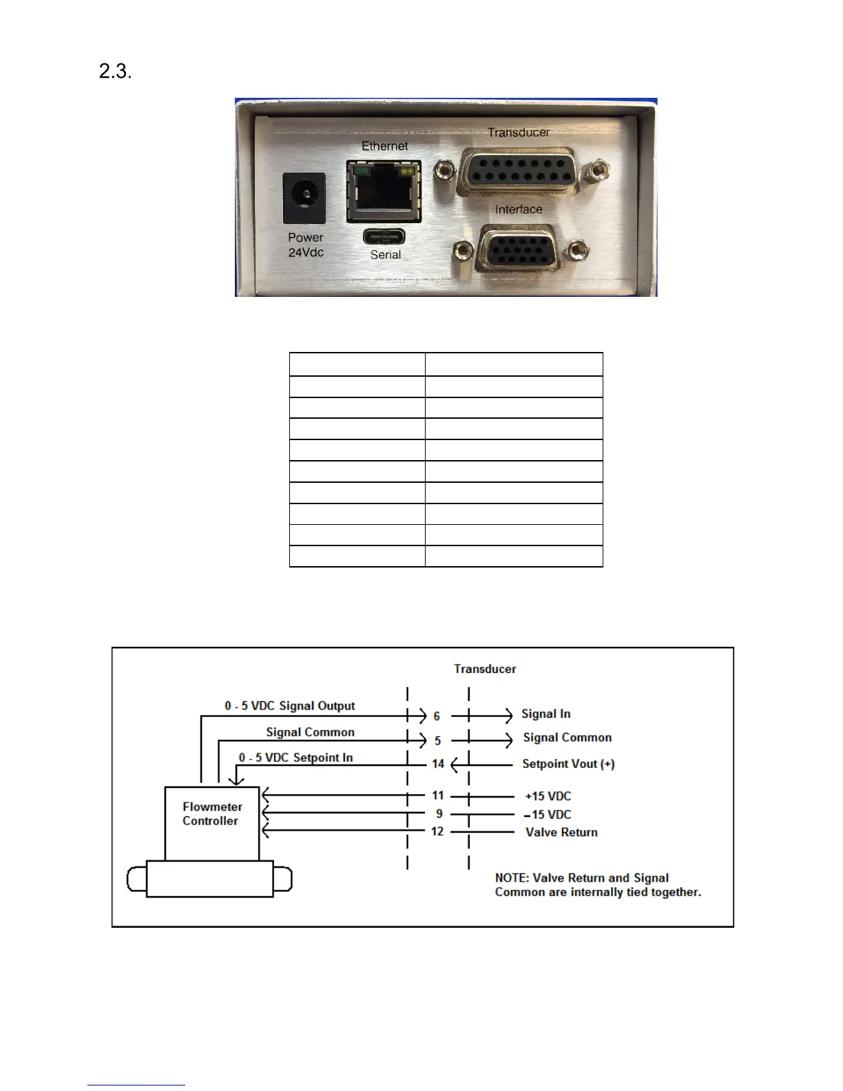
2.3.1. Transducer socket Pinout – 15 Pin 'D' Connector
6 Signal In (Vdc, mA)
9 -15 VDC
11 +15 VDC
13 +24 VDC
All other pins Not Connected
If the transducer is being powered from another source (e.g. a mains powered supply), it will only be necessary
to connect to the two signal pins. Note: The THCD-100 has a floating differential input. For single ended use
(i.e. transducers with differential output) join 0V (pin5) & Signal Return (pin12) at the transducer. Ensure the
common mode input range is not exceeded.