EasyManua.ls Logo

Teleflex MV-2 Series - User Manual

Teleflex MV-2 Series
10 pages
Print Icon
To Next Page IconTo Next Page
Loading...
INSTALLATION MANUAL
Page 1 of 9
Manual # 055001-518 Revision 1
OWNER’S MANUAL
INSTALLATION AND OPERATION OF MV-2
SERIES SIDE MOUNT CONTROL
For Single Station Only
INSTALLER: THESE INSTRUCTIONS CONTAIN IMPORTANT SAFETY INFORMATION AND MUST BE FORWARDED TO THE BOAT OWNER.
These “saftey alerts” alone cannot elim-
inate the hazards they signal. Strict
compliance to these special instruc-
tions when installing, operating or
performing maintanence and using
common sence are the most effective
accident prevention measures.
Hazards or unsafe practices
which COULD result in sever
personel injury or death.
WARNING
!
NOTICE
Throughout this manual, Warnings and Cautions, accompa-
nied by the International Hazard Symbol , are used to alert the manufacturer or installer to special
instructions concerning a particular service or operation that may be hazardous if preformed incor-
rectly or carelessly.
Warnings alone do not eliminate dangers, nor are the a substitute for safe boat handling and proper
accident prevention measures. Observe these alerts carefully!
!
DANGER
!
Immediate Hazards which
WILL result in severe
personel injury or death.
Hazards or unsafe practices
which COULD result in injury,
product and/or property
damage.
CAUTION
!
NOTICE
Information that is important to
the proper installation,
operation and maintenance, but
is not hazard related.
Question and Answer IconNeed help?

Do you have a question about the Teleflex MV-2 Series and is the answer not in the manual?

Summary

Introduction to Morse MV-2 Control

Control Configuration and Adjustment

Control Configuration

Ensures correct control assembly for application, determining push/pull action for transmission and throttle.

Repositioning Shift Arm

Warning: Neutral Safety Switch Relocation

Potential damage to switch and wiring if neutral safety switch is not relocated with shift arm.

Reversing Throttle Action

Throttle Arm and Dwell Block Adjustment

Ensures correct throttle arm and dwell block alignment for push or pull to open throttle.

Mounting Location Guidelines

Shift Cable Connection Procedures

Caution: Shift Cable Pivot Placement

Correct pivot placement ensures equal shift cable travel for proper forward/reverse action.

Shift Lever and Transmission Coincidence

Control shift lever must match transmission lever positions for forward, neutral, and reverse.

Throttle Cable and Neutral Safety Switch Connections

Throttle Cable Connection

Securing throttle cable pivot and lubricating for smooth operation.

Neutral Safety Switch Connection

Connecting the neutral start switch between ignition and starter solenoid.

Mounting Control and Cable Routing

Routing cables straight, avoiding sharp bends, and securing the control unit.

Engine Connection and Adjustment

Caution: Transmission Stop Jamming

Avoid jamming transmission stop to prevent wear, heavy feel, or damage to cable/gear.

Throttle Cable Adjustment for Idle

Adjust throttle cable to ensure engine remains at idle when shifting.

Preliminary Checks and Operation

Neutral Interlock Operation

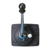
Lifting collar under ball knob to disengage neutral interlock for lever operation.

Caution: Shifting Engine Not Running

Do not force shift when engine is not running to prevent damage.

Warning: Quick Forward to Reverse Shifts

Stay in idle or neutral until boat loses headway before shifting from forward to reverse.

Maintenance Recommendations

Periodic Cleaning and Lubrication

Wipe metallic parts with oil, wash and wax lever, lubricate moving parts with marine grease.

Cable and Connection Inspection

Examine cables and connections for damage, wear, or corrosion; replace as needed.

Neutral Safety Switch and Wiring Check

Check switch for proper function and wiring for abrasion to prevent shorts.

Teleflex MV-2 Series Specifications

General IconGeneral
BrandTeleflex
ModelMV-2 Series
CategoryMarine Equipment
LanguageEnglish