Detailed Operation Cont’d
Offset Trim. Provides for calibrating the low level ADC converter accuracy. The screen shows the output voltage of the detector, and
the Trim level is set by adjusting for zero voltage with no RF power applied.
Hi/Lo Trim. This screen allows the matching of the direct and divided inputs to the ADC to account for any slight variations in the
precision divider.
Master Trim. Adjusts the overall gain for power readout for all frequencies.
Fine Trim. Adjusts gain by band for power readout, indexed by frequency. Frequency is determined automatically by a built-in frequency
counter.
Counter Calibration. Allows synchronizing the LP-100A clock with an external reference.
Normal Operation
In normal operation, the LP-100A is left in the Normal mode. You’ll notice that the screen dims to 25% one second after powering up or
when transmission ends. If Peak power mode is selected and the hold time is set for 1 second or more, it dims at the end of the hold
period. This is part of the screen saver, and is designed to maximize display life. All other modes provide full brightness as preset in
Setup, since they are not used nearly as much as the Normal mode.
For SSB or CW operation, you should use the Peak mode. This mode will show peak power and SWR and hold them for the preset
hold time unless a higher peak is detected, at which time the timer resets. Both the numerical value is held, plus a “sticky bar” in the
bargraph. This lets you see your maximum peak, but still allows the bargraph to follow your transmitted power at very high speed. Do
not use this mode for steady-state power or SWR measurements, as it will be affected by momentary power fluctuations that many
modern rigs have.
The peak power reading can be as much as 30% higher than steady-state power readings taken in the Average mode. This is because
of the ability of the transmitter or amplifier to deliver short bursts of higher power due mainly to power supply regulation issues. This is
especially true of older amplifiers with unregulated power supplies, but also is affected by the ALC timing characteristics of modern rigs
in both CW and SSB. The peak detector in the LP-100A is very fast, and will grab even the smallest peak. Peak SWR will show values
a little higher than steady-state at times due to the wide dynamic range of the LP-100A. There is more about this in the Appendix.
As power drops to below 100 mW during speech, the SWR detector can sometimes grab a higher peak because of the lower accuracy
at extreme low power levels. The worst-case error in this case should be < .10. For best accuracy during measurements, use the
average mode and at least .5 watts of power. The directivity of the LP-100A can easily be greater than 40 dB as you may have noticed
during calibration, even at low power.
For amplifier tuning, you should switch to Tune mode for fast update of both bargraph and numerical readout. The bargraph sampling in
the LP-100A is about 60 samples/second, and it will display a single dit at 100 wpm, or a string of pulses as with a pulser or keyer set
for high speed. Full accuracy should be attainable down to about 500 mW for both power and SWR. Good accuracy should still be
maintained down to < 100 mW. Note. For antenna tuner adjustment, the Average mode provides the best numerical readout, or
dBm/RL if you prefer peaking rather than dipping.
Normally, the SWR Alarm should be set for 2.0:1 unless you purposely operate with an antenna that is close to 2.0:1 SWR. It is up to
you whether to enable the Piezo transducer, by using JP1. In any case, it is recommended that you loop your amplifier PTT through the
LP-100A. This not only helps protect your amplifier, but also the coupler in the LP-100A… especially if you have an older amplifier
which is capable of delivering full power into a high SWR load.
The other normal settings include NET power, 12dB bargraph range bargraph decay of “Off”. You may find, however, that you prefer to
use a slower decay for a smoother response. The choice of 36-bar or 60-bar style for the bargraph depends on your personal
preferences and needs.
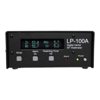
Vector Mode
In the vector mode, you can see the impedance of the load in two ways.
The top line of the display shows the magnitude and phase of the
complex impedance, and the lower line shows the resistive and reactive
components, ie. R + jX. It is important to note here that the sign of the
reactive, or imaginary component cannot be determined automatically by
the LP-100A.
 Loading...