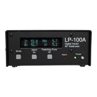
Calibration Cont’d
The first step in Calibration is to make sure that you have the correct serial number range set. This compensates for a number of
factors that may have changed slightly from run to run of the hardware. Also check the maximum power range selected in the Setup
screens.. It also sets the maximum power to match your coupler. There are six couplers currently available for the LP-100A, with more
to come. The standard unit is the LPC1 3KW, 160-6m coupler.
Impedance Calibration
Calibration is done in a couple of steps. First the impedance measurement system is calibrated, and then power levels are calibrated.
The required tools for this calibration are a high quality 50 ohm dummy load, a high quality power meter or other method of determining
power as described in the text and a short coaxial line of known electrical length. A second dummy load is also desirable for calibrating
the slope of the gain detector for impedance, but not absolutely necessary as this adjustment seems to vary only slightly from meter to
meter. I normally do calibration at 100W, but very close to full accuracy can be had with power as low as 5W, and somewhat reduced
accuracy is attainable down to <1W.
I am working on a “calibrator” design which would use inexpensive 1% thick film resistors or 5% metal oxide resistors to provide
switchable 50/25 ohm impedance with a 10W rating. It would include a diode peak detector for measuring power with a calibrated table
of voltage vs. power. I am also testing a method of using a 6’ long length of RG-59U which, when terminated with a 50 ohm dummy
load, produces a known complex impedance. This provides a more accurate way of setting the Gain and Phase slope adjustments, and
takes into account coupler variations as opposed to the delay line method. I have characterized readily available and inexpensive
cables available from Jameco, Radio Shack and Mouser, and will provide part numbers. The cables are BNC-to-BNC, and may require
UHF adapters if you don’t already have them. These are also available from the above suppliers.
If you don’t have a good way to measure your dummy load, you can measure the resistance at DC using a DMM. If you know the load
to be low-inductance through 6m, this will give a reasonable approximation. If you are looking for a high quality dummy load, check out
www.ridgeequipment .com. They have some excellent surplus loads for as little as $10.
The first screen is the Gain Zero Trim screen. This allows for band-by-band balancing of the gain detector. To do this, connect your
dummy load to the ANT connector on the LP-100A coupler. Starting with the lowest band you can transmit on, key the transmitter.
Adjust the Cal constants using the Dn/Up buttons until the displayed resistance matches your dummy load, then unkey the transmitter.
Repeat this procedure for all bands.
Advance to the Phase Zero screen and repeat the procedure for each band, this time adjusting for a phase of zero degrees. There will
probably be some jitter in this case. Just adjust so that the average setting is zero.
The next adjustment screen is Phase Slope. This adjustment sets the slope of the transfer curve of the phase detector so that the
measurement limits are correct. The above Zero adjustment ensures that zero degrees reads close to zero. This adjustment ensures
that higher phase delays display accurately. Together they define the slope of the phase detection curve.
As mentioned in the Overview, adjusting the Phase Slope is simply a matter of matching the reading to a known delay line value. Again,
the formula for determining delay in degrees is…
Phase Delay (Degrees) = (360*L*F)/(984*VF)
Where L is in feet and F in MHz. VF would generally be 0.66 for polyethylene dielectric. Foam dielectrics generally have a VF of about
.80. Check for the correct value of the coax type/brand you are using. A 6’ length with poly dielectric will provide a delay of near 45
degrees at 14 MHz. This is a good range to use, as it places the phase display at about midrange.
Insert the delay line into the Current cable between the controller and coupler, using a BNC barrel connector. With a 50 ohm load, the
phase should read close to the calculated value in degrees. If not, use the Dn/Up buttons to adjust the reading to the correct value.
Leaving this setting at the default 1.000 will result in a maximum phase error of a few degrees over most of the frequency range.
The last impedance adjustment screen is called Gain Slope. This sets the slope of the gain detector so that it is linear with increasing Z.
The adjustment requires a load other than 50 ohms, A convenient value is 25 ohms, which can be created easily by paralleling two 50
ohm loads using a “T” connector. It is important when making this adjustment that there is no coax between the 25 ohm load and the
coupler “Load” connector, otherwise the line will transform the 25 ohm resistive load to some mixed R+jX value. The easiest way to do
this is to screw a UHF Tee connector directly to the Load connector, and then use adapters or lengths of 50 ohm coax to connect to the
two 50 ohm loads. With the transmitter set to 20m, apply power and see what the impedance reads on this screen. If the displayed
value is slightly higher or lower than the actual value, adjust the Dn/Up buttons to match the load’s actual Z (or resistance on a DMM). If
a 25 ohm load reads 100 ohms, you have the current and voltage cables crossed. Correct this and start calibration over from the top.
Remember to return to a 50 ohm load after this test. The expected trim value should be in the range -.0004 to +.0004, and will usually
be even closer than that. Leaving this adjustment at 0.0000 will result in a maximum error of a few tenths of an ohm.
 Loading...