N
N N
G G
L1
L2
L1 L3L2
L3
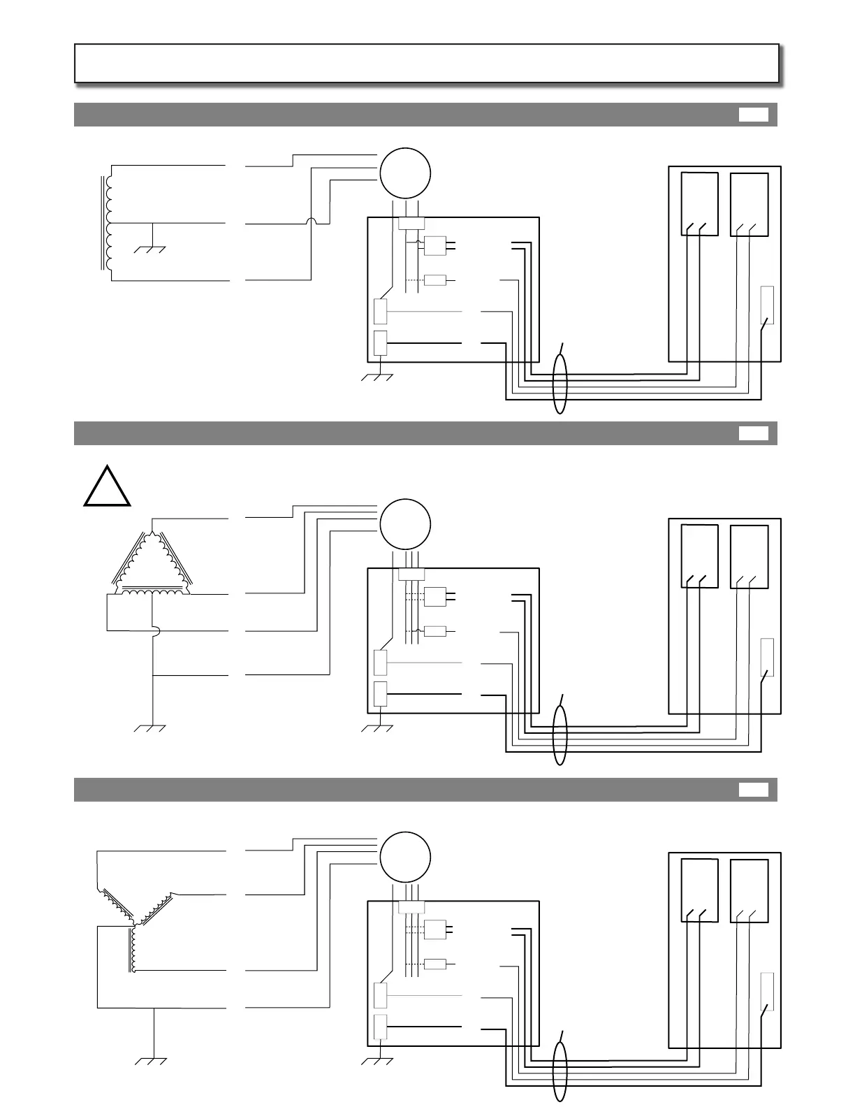
208V between any 2 Legs
Meter
Breaker Panel
120V between any Leg and N
40A
20A
Any Leg
Any 2 Legs
N
N N
G G
L2
L3
“Stinger” or “High Leg”
NOT USED!
L1 L3L2
L1
240V between any 2 legs
120V between L1 and N
120V between L2 and N
! - 208V between L3 and N - !
Meter
Breaker Panel
40A
20A
L1 or L2
! Never L3 !
Never connect the station to L3. The 3rd Leg of delta is 208Volts with respect to Neutral and will trip the GMI !
L1 or L2
! Never L3 !
N
N N
G G
L2
L1
L1 L2
L1
L1
or
L2
N
L2
Meter
Breaker Panel
UP100J Station
40A
20A
G
L1 or L2
L1 & L2
240V
120V
Level-2 Level-1
L1
L1
or
L2
N
L2
UP100J Station
G
240V
120V
Level-2 Level-1
L1
or
L2
Any
Leg
Any
other
Leg
N
UP100J Station
G
240V
120V
Level-2 Level-1
!
240V between L1 and L2
120V between L1 or L2 and N
Size conduit to carry ve
(5) wires:
(4) 30 Amp continuous
load rated conductors,
and (1) earth ground
Size conduit to carry ve
(5) wires:
(4) 30 Amp continuous
load rated conductors,
and (1) earth ground
Size conduit to carry ve
(5) wires:
(4) 30 Amp continuous
load rated conductors,
and (1) earth ground
240/120V SINGLE Split Phase (preferred service)
240V 3-Phase, DELTA-Connected, one leg center tapped (diculty balancing multiple stations)
208V 3-Phase, WYE-Connected (attention to balancing required for multiple stations)
Page 5
Service Wireing Options:
5A
5B
5C
KIT302-IM-20140501
 Loading...