“INSTALLATION” section of this manual). Otherwise with inclined or uneven 4.3 INTERLOCK AND SAFETY FUNCTIONS
floors or moveable supporting surfaces there is the danger of tipping.
- Never lift the spot-welder unless explicitly required by the “INSTALLATION” 4.3.1 PTE Models
section of this handbook. Thermal safeguard.
Triggers if the spot-welder overheats due to insufficient flow or lack of cooling water or to
an excessively heavy duty cycle.
- IMPROPER USE
Triggering is indicated by the yellow LED lighting up on the control panel.
It is dangerous to use the spot-welder for any other purpose than that for
&
EFFECT:current shutdown (welding disabled).
which it is designed (spot resistance welding).
RESET : automatic when temperature returns within allowed limits (yellow LED goes
off).
4.3.2 PCP Models
General switch
The safeguards and moveable parts of the spot-welder casing should all be in
- Position ” O ” = open, can be padlocked (see chapter 1).
position before connection to the power supply.
WARNING: All manual operations on moveable accessible parts of the spot
WARNING! In position ”O” = internal power supply cable terminals (L1 + L2) are
welder, for example:
live.
- Electrode replacement or maintenance
- Position ”I” = closed: the spot welder is in STAND BY mode (green LED on ).
*
- Adjusting the position of the arms or electrodes
SHOULD BE CARRIED OUT WITH THE SPOT-WELDER SWITCHED OFF AND
Emergency function: while the spot-welder is running (opening the switch from ”I” =>
DISCONNECTED FROM THE POWER SUPPLY (MAIN SWITCH LOCKED TO “O”
to ”O” position), the spot-welder will shut down, in safety mode.
USING PADLOCK WITH KEY TAKEN OUT for PNEUMATIC CYLINDER-operated
- current off;
models).
- electrodes opening up (cylinder discharging);
- automatic re-start disabled.
2. INTRODUCTION AND GENERAL DESCRIPTION
Start-up push-button
(
You must push this button in order to control the welding operations (from the pneumatic
2.1 INTRODUCTION
pedal) in each one of the following conditions:
Column spot welders with downward curvilinear electrode for resistance welding (single
- whenever the general switch has shut off (position ”O” => position ”I”);
spot).
- whenever the safety/protection devices have triggered;
Electronic power control (thyristors) integrated with timer and start current limiter.
- whenever the (electric and compressed air) power supply returns after being cut off
Thermal safeguard with indicators (overload or cooling water failure).
due to a fault or disconnection.
Operation:
- ”PTE” models: mechanical, equipped with pedal with adjustable lever length;
Cycle selector
/
- ”PCP” models: pneumatic, equipped with double effect cylinder controlled by a
#$
pedal valve; operation shutdown due to power failure and/or compressed air failure.
- Cycle : it allows the control of the spot-welder (from the pneumatic pedal)
#
without welding. It is used to move the arms and to close the electrodes without
2.2 OPTIONAL ACCESSORIES
power supply.
- Arm pair, length 500mm, complete with electrode holders and standard electrodes.
- Arm pair, length 700mm, complete with electrode holders and standard electrodes.
FURTHER RISKS! Be aware that even in this machine mode the risk of crushing
- Curved electrodes.
the upper limbs exists. (see chapter on safety).
- Closed circuit water cooling system (suitable for PTE or PCP 18 only).
- Cycle (normal welding cycle) enables the spot-welder to make the weld.
$
3. TECHNICAL DATA
Thermal safeguard
Triggers if the spot-welder overheats due to insufficient cooling water flow rate or to an
3.1 RATING PLATE (FIG.A)
excessively heavy duty cycle.
The main data relating to use and performance of the spot-welder are summarised on
This intervention is signalled by the yellow LED located on the control panel.
the rating plate and have the following meanings:
&
EFFECT: current off (welding disabled).
1- Number of phases and frequency of power supply.
RESET: manual (push the button ) after the temperature returns within the allowed
2- Power supply voltage.
(
limits (yellow LED switches off).
Compressed air safety switch
Triggers if there is a compressed air pressure drop or failure (p<2.5 ÷ 3 bar). This
intervention is signalled by the gauge (0 ÷ 3 bar) located on the compressed air input
system.
EFFECT: movements blocked: electrodes opening up: cylinder released.
Current off: welding disabled.
RESET: manual (push button ) after the pressure reaches the allowed limit. (On
the gauge: >>3 bar).
(
15- Safety symbols, the meanings of which are given in chapter 1 “General safety rules
5. INSTALLATION
for resistance welding”.
______________________________________________________________________________________________________________________
Note: The rating plate shown is an example to show the meaning of the symbols and
WARNING! CARRY OUT ALL INSTALLATION OPERATIONS AND
numbers; the exact technical specifications of your spot-welder can be found on the
ELECTRICAL AND PNEUMATIC CONNECTIONS WITH THE SPOT-WELDER
rating plate of the spot-welder itself.
COMPLETELY SWITCHED OFF AND DISCONNECTED FROM THE POWER
SUPPLY OUTLET. THE ELECTRICAL AND PNEUMATIC CONNECTIONS MUST BE
3.2 OTHER TECHNICAL DATA (FIG.B)
MADE ONLY AND EXCLUSIVELY BY AUTHORISED, SKILLED PERSONNEL.
______________________________________________________________________________________________________________________
5.1 PRELIMINARY OPERATIONS
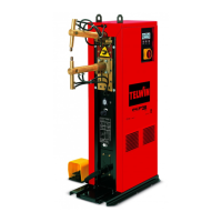
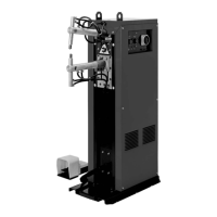
4. DESCRIPTION OF THE SPOT-WELDER
Unpack the spot-welder, assemble the separate parts as indicated below.
4.1 SPOT-WELDER ASSEMBLY AND DIMENSIONS (FIG. C)
5.2 LIFTING THE SPOT-WELDER (FIG. E)
The spot-welder should be lifted with a double cable and hooks, using the eyebolts
4.2 CONTROL AND ADJUSTMENT DEVICES
fitted for this purpose.
It is absolutely prohibited to sling the spot-welder in a different way from the one we
4.2.1 Control panel (FIG. D1)
prescribed (e.g. on arms or electrodes).
1- General switch (in PCP models with emergency stop functions and possibility of
padlock in “O” position: padlock and keys supplied).
5.3 POSITION
2- Indicator LED's:
The installation area must be sufficiently large and without obstacles, suitable for
a) (green) machine powered, control board “ON”,
*
ensuring safe access to the control panel and to the work area (electrodes).
b) (green) welding “ON” (control and thyristor model activated),
Ensure that there are no obstacles near the cooling air inlets and outlets and that no
%
conductive dusts, corrosive vapour, humidity, etc. can be sucked in.
c) (yellow) thermal safeguard triggered: welding disabled (in PCP models
Position the spot-welder on a plane surface made of homogeneous and compact
&
arm operation is also disabled).
material (floor made of concrete or similar physical characteristics).
3- ”POWER” : welding current adjustment potentiometer;
Fasten the spot-welder to the floor by means of four M10 bolts, using the special holes
4- ”TIMER” : welding time adjustment potentiometer;
on the base; each individual element anchoring the spot-welder to the floor must
5- start-up/reset push-button (PCP models);
(
guarantee a tensile strength of at least 60 Kg. (60daN).
6- pressure only (machine does not weld) / welding device selector (PCP
/
$
Maximum load
#
models only).
The maximum load that can be applied to the lower arm (concentrated on the electrode
axis) is 35 Kg. (35daN).
4.2.2 Compression nut (FIG. D2)
This can be reached by opening the gate on the rear of the spot-welder; it is used to
regulate the force exerted by the electrodes by adjusting the pre-load of the spring.
5.4 CONNECTION TO THE MAIN POWER SUPPLY
5.4.1 Warnings
Before making any electrical connection, make sure the rating data of the spot-
3- Mains power with permanent running (100%).
4- Rated mains power with 50% duty cyde.
5- Maximum loadless voltage over electrodes.
6- Maximum current when electrodes are shorted.
7- Current to secondary when running permanently (100%).
8- Gauge and length of arms (standard).
9- Minimum and maximum adjustable electrode force.
10- Rated pressure of compressed air supply.
11- Pressure of compressed air supply needed to obtain maximum electrode force.
12- Cooling water flow rate.
13- Rated pressure drop for coolant liquid.
14- Weight of welding device.
 Loading...