G) Connect the powersupply cableto the 230Vac powersupply.
during testing prevent contact with the metal part of
the torch because of the presence of high voltages that are
hazardousto the operator.
Switch on the machine, gradually increase the power supply
voltagefrom 0V to 230Vacand makesure that:
- the pre-charge relays onthe primary board close;
- the fanstartsoperating correctly;
- the waveform displayed on the oscilloscope resembles
andthe frequency isequal to +32.5KHz ±20%;
±
±
WARNING!
A) Loadless test:
Fig. E
1.2 Scheduled tests
- the output voltage over dinse + and dinse is equal to 95Vdc
10%.
- set up the ohmic load with the switch settings as in the table in
;
- on the front panel position the current potentiometer on
minimum(turnanti-clockwiseas farasit will go);
- switch onthe main switch;
- startup on the ohmic load and makesurethat:
- the waveforms displayed on the oscilloscope resemble
thosein ;
- the output current is equal to +5Adc 20% and the output
voltageis equal to +20.2Vdc %.
- switchoffthe ohmic load and switchoff themain switch.
- set up the ohmic load with the switch settings as in the table in
;
- on the front panel position the current potentiometer on approx.
80A;
- start up the ohmic loadand makesure that:
- the waveforms displayed on the oscillscope resemble
thosein ;
- the output current is equal to +80Adc 10% and the output
voltageis equal to +23.2.Vdc 10%.
- switchoff the ohmicload and switchoff the main switch.
- the ohmic load with the switch settings according to the
relevantTechnologymodel (seetablesin );
- on the front panel position the current potentiometer on
maximum(turnclockwiseas farasit will go)
- startup on the ohmic load andmakesure that:
- the waveforms displayed on the oscillscope resemble those in
;
- the output current is equal to +130Adc ±3% and the output
voltageis equal to +25.2Vdc ±5%;if the output current reading
is not 130A ±3%, adjust the current using trimmer IMAX R13
onthe primary board ( ).
B) Rated load test:
fig.G
Fig.F
C) Intermediateload test:
fig.G
Fig.G
A) Ratedloadtest:
Figs.H,I,J,K
Fig.H
fig.3
For the Technology 150
±
±
±10
-15-
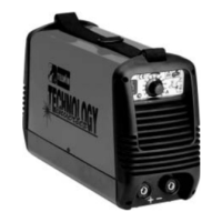
TECHNOLOGY 150-170-200-186CE/GE
TECHNOLOGY 150-170-200-186CE/GE
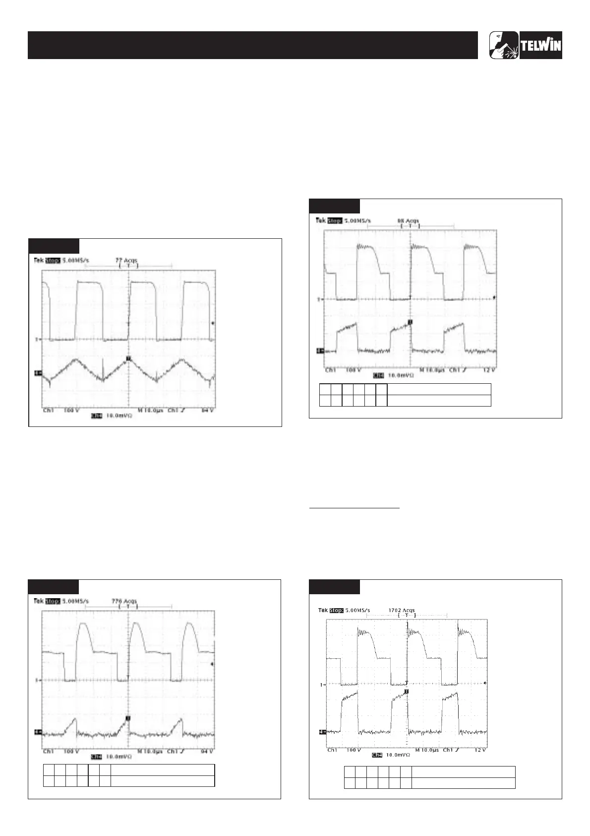
FIGURE E
SETTINGS
· THE FREQUENCY IS
60KHz ±5%;
· AMPLITUDE CH1 IS
340V ±10%;
:
· PROBE CH1 x100;
· 100 V/Div;
· PROBE CH4 =1A;
· 10mV/Div;
· 105 sec/Div.µ
VERIFY THAT
Number switch
Position switch
FIGURE E
6
3
2
1
4
5
333222
FIGURE H
SETTINGS
· THE FREQUENCY IS
32.5KHz ±20%;
· AMPLITUDE CH1 IS
340V ±10%;
· AMPLITUDE CH4 IS
56A ±10%;
:
· PROBE CH1 x100;
· 100 V/Div;
· PROBE CH4 =20A;
· 10mV/Div;
· 10 sec/Div.µ
VERIFY THAT
FIGURE E
FIGURE F
6
3
2
1
4
5
1
0
0
0
0
0
Number switch
Position switch
SETTINGS
· THE FREQUENCY IS
60KHz ±5%;
· AMPLITUDE CH1 IS
340V ±10%;
· AMPLITUDE CH4 IS 7A
±20%;
:
· PROBE CH1 x100;
· 100 V/Div;
· PROBE CH4 =5A;
· 10mV/Div;
· 10 sec/Div.µ
VERIFY THAT
Number switch
Position switch
FIGURE E
6
3
2
1
4
5
2
22
2
1
0
FIGURE G
SETTINGS
· THE FREQUENCY IS
60KHz ±5%;
· AMPLITUDE CH1 IS
340V ±10%;
· AMPLITUDE CH4 IS
26A ±20%;
:
· PROBE CH1 x100;
· 100 V/Div;
· PROBE CH4 =20A;
· 10mV/Div;
· 10 sec/Div.µ
VERIFY THAT