For the Technology 170
For the Technology 200
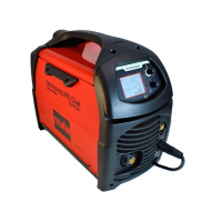
- the waveforms displayed on the oscillscope resemble those in
;
- the output current is equal to +160Adc ±3% and the output
voltageis equal to +26.4Vdc ±5%;if the output current reading
is not 160A ±3%, adjust the current using trimmer IMAX R13
onthe primary board ( ).
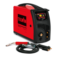
- the waveforms displayed on the oscillscope resemble those in
;
- the output current is equal to +180Adc ±3% and the output
voltageis equal to +27.7Vdc ±5%;if the output current reading
is not 180A ±3%, adjust the current using trimmer IMAX R13
onthe primary board ( ).
Fig.I
fig.3
Fig.J
fig.3
For the Technology 186CE/GE
- the waveforms displayed on the oscillscope resemble those in
;
- the output current is equal to +145Adc ±3% and the output
voltageis equal to +25.8Vdc ±5%;if the output current reading
is not 145A ±3%, adjust the current using trimmer IMAX R13
onthe primary board ( ).
- switchoff the ohmicload and switchoff the main switch.
- set up the dual trace oscilloscope, connecting probe CH1 x
100 to the anode of diode D1 or D2 and probe CH2x100 to the
anode of diode D3 or D5.Earth connections are both made to
thesecondary dissipator;
- remove the multimeter from the OUT+ and OUT- bump
contacts;
- set up the ohmic load with the switch settings according to the
relevantTechnologymodel (seetablesat point 1.2D);
- on the front panel position the current potentiometer R7 to the
maximum (turn the knob clockwise as far as it will go) and
switch onthe main switch;
- activate the static load generator and make sure that the
waveforms displayed on the oscilloscope resemble those in
- deactivate the static load generator and switch off the main
switch.
Set up the ohmic load as shown in the table in and the
current potentiometer on approx. 80A. Position switch SW1 on
HARD (in the centre), start the ohmic load and make sure the
output current reading shows approx. 110A ±10% then returns to
thecurrent setting
.
On the front panel set switch SW1 to SOFT (as low as it will go and
the welding current to maximum). Under the relevant load
Fig.K
fig.3
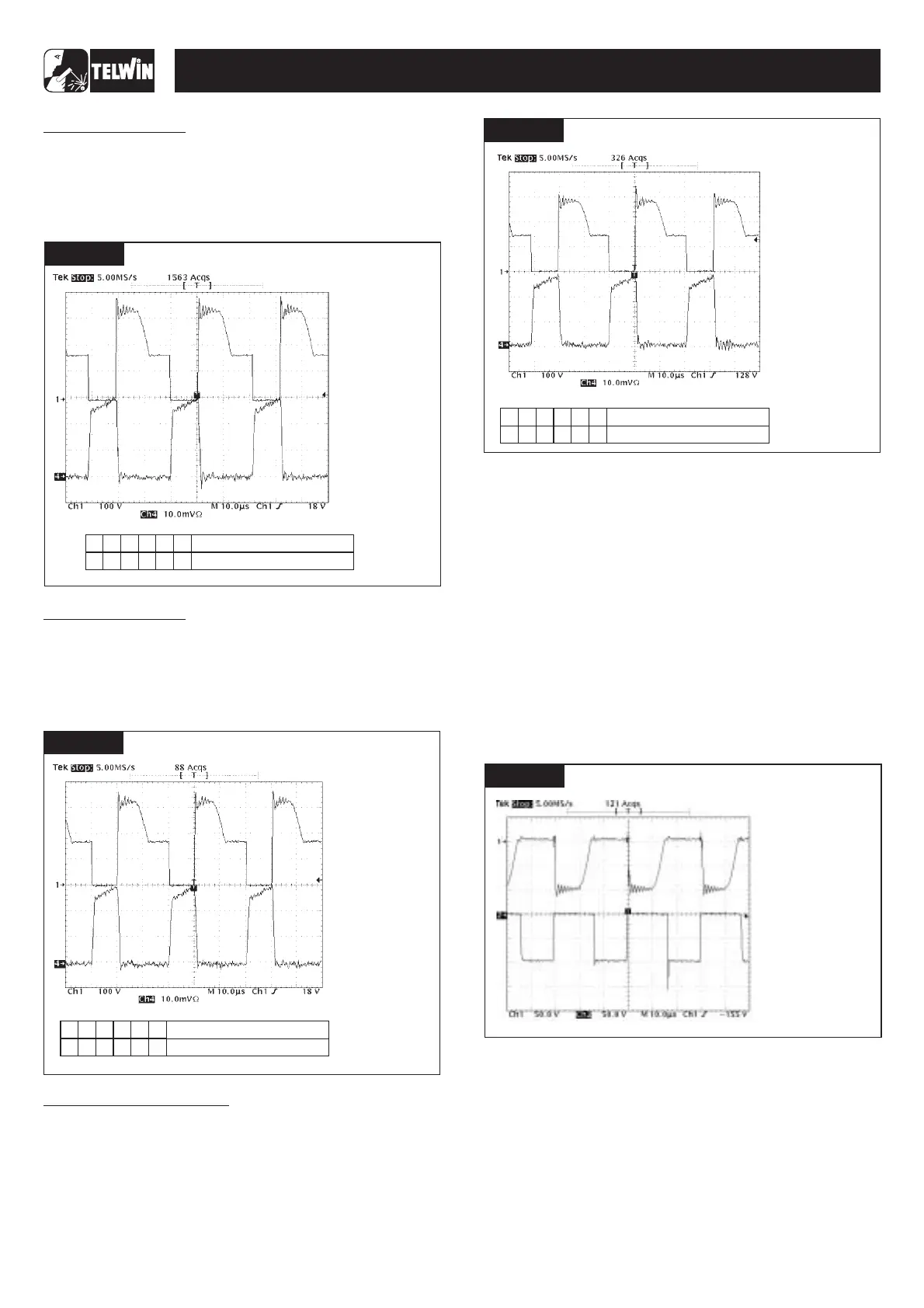
E) Checkingthe secondary diode voltages:
fig.L;
A)Arc Force test
Fig. G
B)Runningtime test andclosingthe machine
1.3 Operational tests
-16-
FIGURE E
6
3
2
1
4
5
333332
FIGURE J
TECHNOLOGY 150-170-200-186CE/GE
Number switch
Position switch
FIGURE E
FIGURE I
Number switch
Position switch
6
3
2
1
4
5
333222
SETTINGS
· THE FREQUENCY IS
32.5KHz ±20%;
· AMPLITUDE CH1 IS
340V ±10%;
· AMPLITUDE CH4 IS
60A ±10%;
:
· PROBE CH1 x100;
· 100 V/Div;
· PROBE CH4 =20A;
· 10mV/Div;
· 10 sec/Div.µ
VERIFY THAT
FIGURE E
6
3
2
1
4
5
333222
FIGURE K
Number switch
Position switch
SETTINGS
· THE FREQUENCY IS
32.5KHz ±20%;
· AMPLITUDE CH1 IS
340V ±10%;
· AMPLITUDE CH4 IS
58A ±10%;
:
· PROBE CH1 x100;
· 100 V/Div;
· PROBE CH4 =20A;
· 10mV/Div;
· 10 sec/Div.µ
VERIFY THAT
SETTINGS
· THE FREQUENCY IS
32.5KHz ±20%;
· AMPLITUDE CH1 IS
340V ±10%;
· AMPLITUDE CH4 IS
60A ±10%;
:
· PROBE CH1 x100;
· 100 V/Div;
· PROBE CH4 =20A;
· 10mV/Div;
· 10 sec/Div.µ
VERIFY THAT
FIGURE E
FIGURE L
SETTINGS
· REVERSE AMPLITUDE
ON CH1
250V.
· REVERSE AMPLITUDE
ON CH2
250V.
:
· PROBE CH1 x100;
· 50V/Div;
· PROBE CH2 x100;
· 50V/Div;
· 10 sec/Div.µ
VERIFY THAT
DOES NOT
EXCEED
DOES NOT
EXCEED