3
User Manual
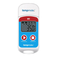
For tempmate.®-M1 Data Logger
03.3 Pause operation
Double click left key to enter the pause status. Under pause status, the device only records time instead of
temperature recording. By double click left key again, the pause operation is canceled and set to normal temperature
recording again.
03.4 Mark operation
Double click the right key to mark an operation. After finishing marking operation – if quickly pause and pause cancel
action is performed - the current marking can be canceled.
Note:
(1)
For one recording trip, the device can support a maximum of 10 marks.
(2)
Under status of pause or sensor disconnected status (when external sensor is configured), the MARK operation is
disabled.
03.5 Stop operation
M1 supports two stop modes(stop when reaches the max. record capacity, manual stop), and the specific stop mode is
determined by parameter setting.
Stop when reaches the max. record capacity: When record capacity reaches the max. record capacity, the logger will
stop automatically.
Manual stop: The device only stops when it is manually stopped except if the battery is under 5%. If the recorded data
reaches to its max. capacity, the data will be overwritten (depends on the setting).
Note:
During the status of data overwriting (ring memory), MARK operation will not be cleared. Saved marks still exist. The
max. MARK events are still “10 times” and every marked data will be saved without clearing during the transport cycle.
03.6 Viewing operation
During tempmate.®-M1 is in recording or stopping status, insert the logger to the computer, the data can be viewed by
the tempbase.® software or the generated PDF report in the USB device.
PDF reports are dierent if there is an alarm setting:
If no alarm setting is programmed, there is no alarm information column and in data table, no alarm color marking,
and at the left upper corner, it displays PDF in the black rectangle.
If the alarm is set as upper/lower alarm, it has an alarm information column, and it has three lines of informations:
upper alarm information, standard zone information, lower alarm information. The upper alarm recording data is
displayed in red, and the lower alarm data is displayed in blue. In the left upper corner, if alarm occurs, the background
of the rectangle is red and displays ALARM inside. If no alarm occurs, the background of the rectangle is green and
displays OK inside.
If the alarm is set as multiple zone alarm in the PDF alarm information column, it could have max. six lines: upper
3, upper 2,upper 1, standard zone; lower 1, lower 2 the upper alarm recording data is displayed in red, and the lower
alarm data is displayed in blue. In the left upper corner, if alarm occurs, the background of rectangle is red and displays
ALARM inside. If no alarm occurs, the background of rectangle is green and displays OK inside.
Note:
(1)
Under all alarm modes, if data table zone for marked data is indicated in green. If the recorded points are invalid
(USB connection (USB), pause data (PAUSE), sensor failure or sensor is not connected (NC)), then the record marking is
gray. And in PDF curve zone, in case of USB data connection (USB), data pause (PAUSE), sensor failure (NC), all of their
lines will be drawn as bold gray dotted lines.
(2)
If the tempmate.®-M1 is connected to the computer during the recording period, it records no data during the
connection time.
 Loading...