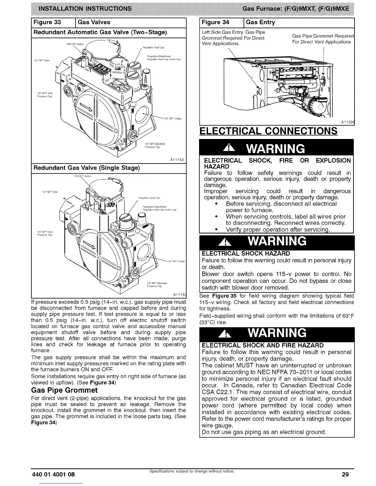
Figure33 /Gas Valves
Redundant Automatic Gas Valve (Two-Stage)
v
ON,OFF Switch
Regulator Seal Cap
RegulatorAdjustment
1,2" NPT Inlet Regulator Seal Cap under Cap
1/8" NPT Inlet
Pressure Tap
1/8" NPT Manifold
Al1152
Redundant Gas Valve (Single Stage)
Regulator Seal Cap
Regulatol Adjustment
Regulator Sea_ Cap l_nder Cap
1/8" NPT In_et
Pressure Tap
1,8' NPT Manifold
Pressure Tap
Al115{
If pressure exceeds 0.5 psig (14-in. w.c.),gas supply pipe must
be disconnected from furnace and capped before and during
supply pipe pressure test. If test pressure is equal to or less
than 0.5 psig (14-in. w.c.), turn off electric shutoff switch
located on furnace gas control valve and accessible manual
equipment shutoff valve before and during supply pipe
pressure test. After all connections have been made, purge
lines and check for leakage at furnace prior to operating
furnace.
The gas supply pressure shall be within the maximum and
minimum inletsupply pressures marked on the rating plate with
the furnace burners ON and OFF.
Some installations require gas entry on right side of furnace (as
viewed in upflow). (See Figure 34)
Gas Pipe Grommet
For direct vent (2-pipe) applications, the knockout for the gas
pipe must be sealed to prevent air leakage. Remove the
knockout, install the grommet in the knockout, then insert the
gas pipe.The grommet is included in the loose parts bag. (See
Figure34)
Figure 34 I Gas Entry
Left Side Gas Entry. Gas Pipe
Grommet Required For Direct Gas Pipe Grommet Required
Vent Applications. For Direct Vent Applications
A1133E
ELECTRICAL CONNECTIONS
ELECTRICAL SHOCK, FIRE OR EXPLOSION
HAZARD
Failure to follow safety warnings could result in
dangerous operation, serious injury, death or property
damage.
Improper servicing could result in dangerous
operation, serious injury, death or property damage.
• Before servicing, disconnect all electrical
power to furnace.
• When servicing controls, label all wires prior
to disconnecting. Reconnect wires correctly.
• Verify proper operation after servicing.
ELECTRICAL SHOCK HAZARD
Failure to follow this warning could result in personal injury
or death.
Blower door switch opens 115-v power to control. No
component operation can occur. Do not bypass or close
switch with blower door removed.
See Figure 35 for field wiring diagram showing typical field
115-v wiring. Check all factory and field electrical connections
fortightness.
Field-supplied wiring shall conform with the limitations of 63°F
(33°C) rise.
ELECTRICAL SHOCK AND FIRE HAZARD
Failure to follow this warning could result in personal
injury, death, or property damage.
The cabinet MUST have an uninterrupted or unbroken
ground according to NEC NFPA 70-2011 or local codes
to minimize personal injury if an electrical fault should
occur. In Canada, refer to Canadian Electrical Code
CSA C22.1. This may consist of electrical wire, conduit
approved for electrical ground or a listed, grounded
power cord (where permitted by local code) when
installed in accordance with existing electrical codes.
Refer to the power cord manufacturer's ratings for proper
wire gauge.
Do not use gas piping as an electrical ground.
440 01 4001 08 Specifications subject to change without notice. 29
 Loading...


