FURNACEMAY NOT OPERATE HAZARD
Failure to follow this caution may result in intermittent
furnace operation.
Furnace control must be grounded for proper operation
or else control will lock out. Control must remain
grounded through green/yellow wire routed to gas
valve and manifold bracket screw.
115-V Wiring
Furnace must have a 115-v power supply properly connected
and grounded.
NOTE: Proper polarity must be maintained for 115-v wiring. If
polarity is incorrect, control status indicator light flashes rapidly
and furnace does NOT operate.
Verify that the voltage, frequency, and phase correspond to that
specified on unit rating plate. Also, check to be sure that
service provided by utility is sufficient to handle load imposed
by this equipment. Refer to rating plate or Table11 for
equipment electrical specifications.
U.S.A. Installations: Make all electrical connections in
accordance with the current edition of the National Electrical
Code (NEC) NFPA 70 and any local codes or ordinances that
might apply.
Canadian Installations: Make all electrical connections in
accordance with the current edition of the Canadian Electrical
Code CSA C22.1 and any local codes or ordinances that might
apply.
FIRE HAZARD
Failure to follow this warning could result in personal
injury, death, or property damage.
Do not connect aluminum wire between disconnect
switch and furnace. Use only copper wire.
SWITCH
®
Al1146
Use a separate, fused branch electrical circuit with a properly
sized fuse or circuit breaker for this furnace. See Table 11 for
wire size and fuse specifications. A readily accessible means of
electrical disconnect must be located within sight of the
furnace.
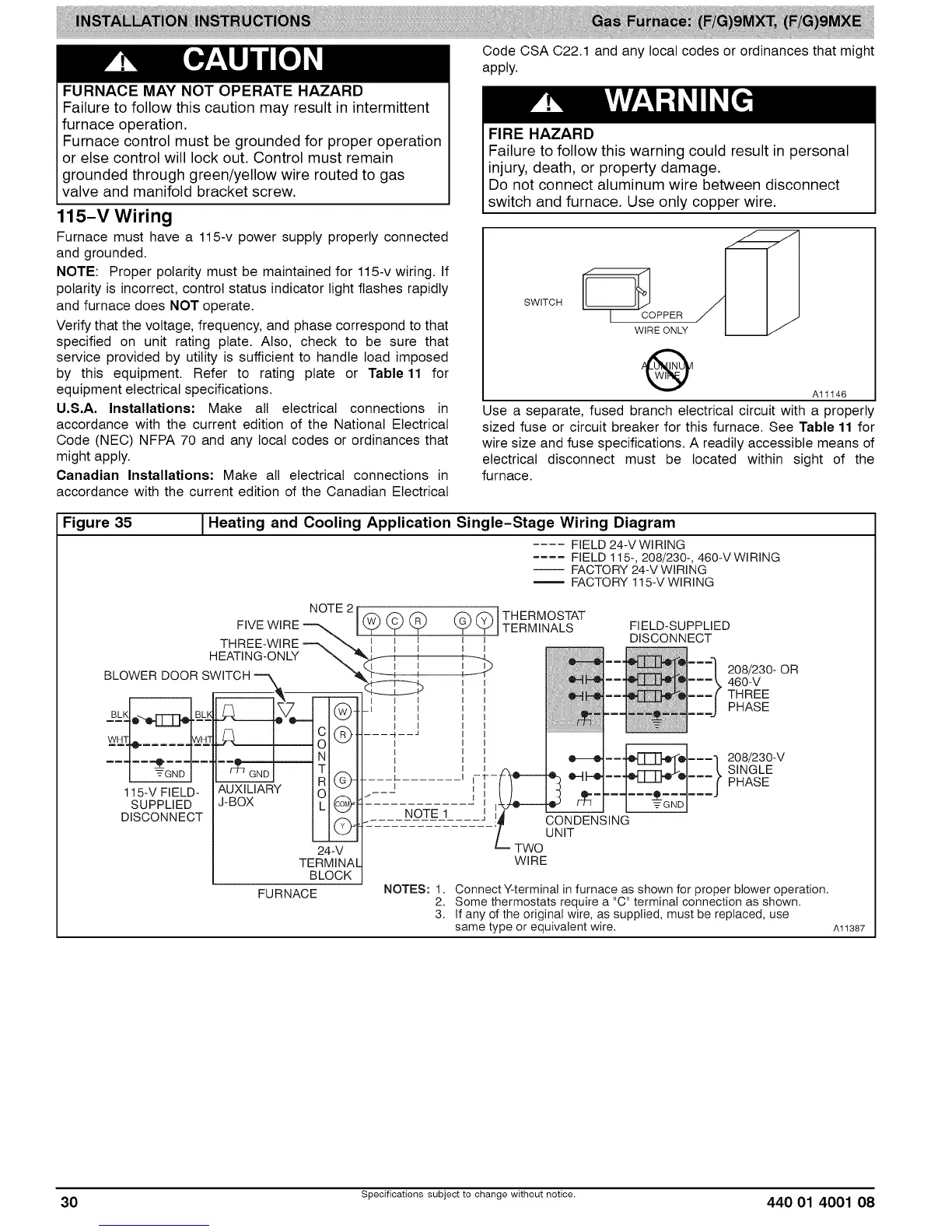
Figure 35 J Heating and Cooling Application
Single-Stage Wiring Diagram
.... FIELD 24-V WIRING
.... FIELD 115-, 208/230-, 460-VWlRING
-- FACTORY24-VWIRING
FACTORY115-VWIRING
NOTE21 f_'__ _ f'_ f3"_]THERMOSTAT
FIVEWIRE _ __ _ _ \_J L_JI TERMINALS FIELD-SUPPLIED
...... DI NNE T
THREE-WIRE--_ _' --' _ tl I I ' SCO C
HEATING-ONLY _ "_ _ I , _.
mmm
BLOWERDOOR SWITCH--m "_"b_ I _ I -_) ............. .... ii 208/230-.... OR
\. _-----k n m=m\ _bu-v
_, "___L__JV n .( THREE
, , r--------_ _ u _ { n ===l PHA_E
BLK BLK _ (_- - I I I ===J
..... I ---I l ...............................
I _GNDI I _ GNDI TI f-_ ! L_Z_ _JL.. J_..I k SINGLE
115-VFIELD''_ AUXILIAR'[Y RIGL_ :: _ ....... i ()- I-1%_----------]_--O--m:l:::f PHASE
SUPPLIED J-BOX LI_ - -N-O-I:E_ 1 I 1_ /-/-/ I -_----GND I
DISCONNECT I ('-C_ -- u !_ CONDENSING
/ UNiT
24-V L__TWO
TERMINAl WIRE
BLOCK
FURNACE NOTES: 1. ConnectY-terminal in furnace as shown for proper blower operation,
2. Some thermostats requirea "C" terminal connection as shown.
3. If any ofthe original wire, as supplied, must be replaced, use
same type or equivalent wire, Al1387
30 Specifications subject to change without notice. 440 01 4001 08
 Loading...


