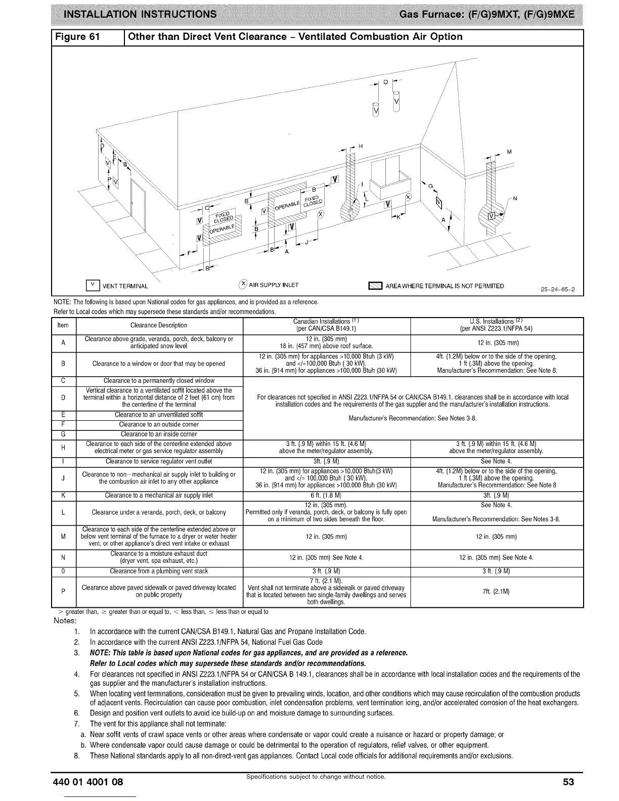
Figure61 _Other than Direct Vent Clearance - Ventilated Combustion Air Option
I
/
H
-fl
tXi AIR SUPPLY INLET E_ AREA WHERE TERMINAL IS NOT PERMITED 25-24-65-2
D VENT TERMINAL \ Yi':_
NOTE:Thefollowing is baseduponNationalcodesfor gas appliances,andis provided as a reference.
Referto Localcodeswhich maysupersedethese standardsand/orrecommendations.
Item
A
B
C
D
E
F
G
H
I
U,S. Installations(z}
(per ANSI Z223.1/NFPA54)
ClearanceDescription
Clearanceabovegrade,veranda,porch, deck.balcony or
anticipatedsnowlevel " 12 in. (305ram)
4ft. (1.2M)belowor to the sideof the opening,
Clearanceto a windowor door that may be opened 1 ft (.3M)abovethe opening.
Manufacturer'sRecommendation:See Note 8.
Canadian Installations(1}
(perCAN/CSAB149.1)
12 in. (305 mm)
18 in. (457 ram)above roof surface.
12 in.(305ram) forappliances >10,000Btuh (3kW)
and </=100,000Btuh ( 30 kW),
36 in. (914 ram)for appliances>100,000Btuh (30 kW)
Forclearances notspecified in ANSIZ223.1/NFPA54 or CAN/CSA B149.1,clearancesshall be in accordancewith local
installationcodes andthe requirementsofthe gas supplierandthe manufacturer'sinstallationinstructions.
Manufacturer'sRecommendation:See Notes 3-8.
Clearanceto a permanentlyclosedwindow
Verticalclearance to a ventilatedsoffit located abovethe
terminalwithin a horizontaldistanceof 2 feet (61 cm)from
the centedineof the terminal
Clearanceto an unventilatedsoffit
Clearanceto an outsidecorner
Clearanceto an inside corner
Clearanceto each sideof the centerline extendedabove
electrical meteror gasservice regulator assembly
Clearanceto serviceregulatorvent outlet
Clearanceto non mechanicalair supplyinlet to buildingor
the combustionair inletto any other appliance
Clearanceto a mechanicalair supplyinlet
3 ft. (.9 M) within15 ft. (4.6 M) 3 ft. (.9 M) within15 ft. (4.6 M)
abovethemeter/regulatorassembly, abovethemeter/regulatorassembly.
3ft. (.9 M) See Note 4.
12in. (305ram)for appliances>10,000 Btuh(3 kW) 4ft. (1.2M)belowor to the sideof the opening,
J and </= 100,000Btuh (30 kW), 1 ft (.3M)abovethe opening.
36 in. (914 ram)for appliances>100,000Btuh (30 kW) Manufacturer'sRecommendation:See Note8
K 6 ft. (1.8 M) 3ft. (.9 M)
12 in. (305 ram). See Note 4.
L Clearanceundera veranda,porch, deck,or balcony Permittedonly if veranda,porch, deck, orbalcony is fully open
on a minimumof two sides beneaththe floor. Manufacturer'sRecommendation:See Notes3-8.
Clearanceto each sideof the centerline extendedaboveor
M belowventterminal ofthe furnace to a dryer or waterheater 12 in. (305 ram) 12 in. (305 ram)
vent, orother appliance'sdirectvent intakeor exhaust
Clearanceto a moisture exhaust duct
N (dryer vent,spa exhaust, etc.) 12 in. (305 ram)See Note 4. 12 in. (305 ram)See Note 4.
0 Clearancefroma plumbingvent stack 3 ft. (.9M) 3 ft. (.9M)
7 ft. (2.1 M).
Clearanceabovepaved sidewalkor paveddrivewaylocated Vent shallnot terminateabove a sidewalkorpaved driveway 7ft. (2.1M)
P on publicproperty thatis locatedbetweentwo single-familydwellingsandserves
both dwellings.
> greaterthan, > greaterthan or equalto, < lessthan, < less than or equalto
Inaccordancewiththecurrent CAN/CSAB149,1,NaturalGasand PropaneInstallationCode,
Inaccordancewiththecurrent ANSIZ223,1/NFPA54, NationalFuelGasCode
NOTE: Thistable isbaseduponNationalcodesfor gasappliances,and areprovidedas areference.
Referto Loca/codes whichmaysupersedethesestandardsand/orrecommendations.
4. ForclearancesnotspecifiedinANSI Z223,1/NFPA54orCAN/CSAB 149,1,clearancesshallbe in accordancewith localinstallationcodesandthe requirementsofthe
gassupplierandthe manufacturer'sinstallationinstructions,
5. Whenlocatingventterminations,considerationmustbe giventoprevailingwinds,location,and otherconditionswhichmaycauserecirculationofthecombustionproducts
ofadjacentvents, Recirculationcancause poorcombustion,inlet condensationproblems,ventterminationicing, and!oracceleratedcorrosionof the heatexchangers.
6. Designand positionventoutletsto avoid icebuild-upon and moisturedamageto surroundingsurfaces,
7. The ventfor thisapplianceshallnotterminate:
a, Nearsoffitvents ofcrawl spaceventsor otherareas wherecondensateor vaporcould create a nuisanceor hazardor propertydamage;or
b, Where condensatevapor couldcause damageor couldbe detrimentalto the operationof regulators,reliefvalves,or otherequipment,
8. These Nationalstandardsapply to all non-direct-ventgas appliances.ContactLocalcodeofficialsfor additionalrequirementsand!orexclusions.
Notes:
1,
2,
3,
440 O1 4OO1 08 Specifications subject to change without notice. 53
 Loading...


