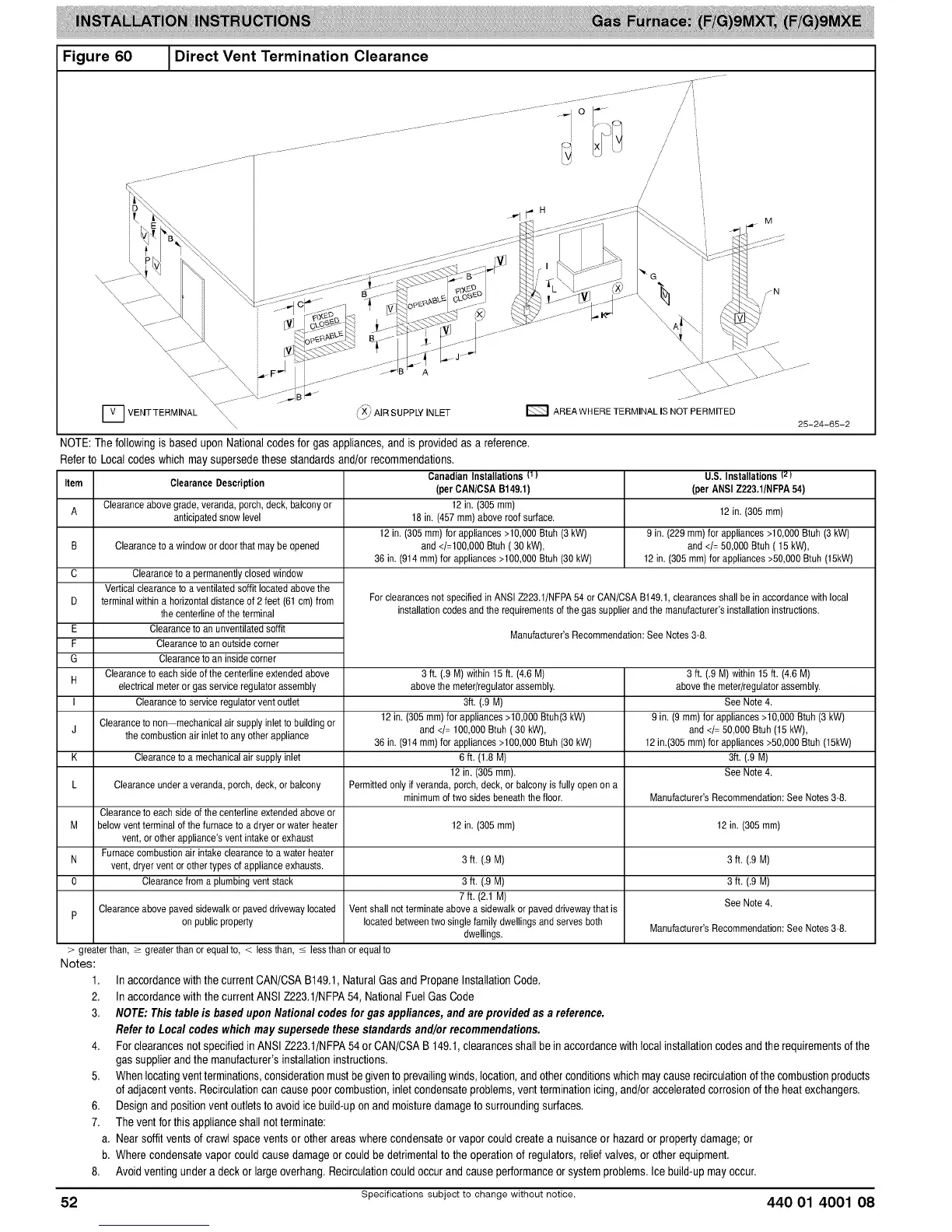
Figure 60 1Direct Vent Termination Clearance
AREAWHERE TERMINAL IS NOT PERMITED
25-24-65-2
[] VEHTTERMINAL \\\\\ (_ AIRSUPPLYINLET
NOTE: The following is based upon National codes for gas appliances, and is provided as a reference.
Refer to Local codes which may supersede these standards and/or recommendations.
Item ClearanceDescription
A Clearanceabovegrade,veranda,porch, deck,balconyor
anticipatedsnow level 12 in. (305 ram)
9 in. (229mm) for appliances>10,000 Btuh (3kW)
Clearanceto a window or door thatmay be opened and </= 50,000Btuh ( 15 kW),
12 in. (305 ram)for appliances>50,000Btuh(15kW)
B
C Clearanceto a permanentlyclosedwindow
Verticalclearanceto a ventilatedsoffit locatedabovethe
D terminalwithina horizontal distanceof 2feet (61 cm)from
the centerlineofthe terminal
E Clearanceto an unventilatedsoffit
F Clearanceto an outsidecorner
G Clearanceto an inside corner
Clearanceto eachside of the centerlineextended above
H
electricalmeteror gas service regulator assembly
I Clearanceto service regulatorvent outlet
Clearanceto non mechanicalair supplyinlet to building or
the combustionair inletto any other appliance
Clearanceto a mechanicalair supplyinlet
CanadianInstallations {1)
(perCAN/CSAB149.1)
12 in. (305 ram)
18 in. (457 ram)above roof surface.
12 in.(305mm) forappliances >10,000Btuh (3kW)
and </=100,000Btuh ( 30 kW),
36 in. (914 mm) for appliances>100,000Btuh (30 kW)
U.S. Installations Iz)
(per ANSI Z223.1/NFPA54)
Forclearances not specifiedin ANSI Z223.1/NFPA54 orCAN/CSA B149.1,clearances shallbe in accordancewith local
installationcodes andthe requirementsofthe gas supplierandthe manufacturer'sinstallationinstructions.
Manufacturer'sRecommendation:See Notes 3-8.
3 ft. (.9 M) within15 ft. (4.6 M) 3 ft. (.9 M)within 15 ft. (4.6 M)
abovethemeter/regulatorassembly, abovethe meter/regulatorassembly.
3ft. (.9 M) See Note 4.
12in. (305mm)for appliances>10,000 Btuh(3 kW) 9 in. (9 ram)for appliances>10,000 Btuh(3 kW)
J and </= 100,000Btuh (30 kW), and </= 50,000Btuh (15 kW),
36 in. (914 mm) for appliances>100,000Btuh (30 kW) 12 in.(305 ram)for appliances>50,000 Btuh(15kW)
K 6 ft. (1.8 M) 3ft. (.9 M)
12 in. (305 mm). See Note 4.
L Clearanceundera veranda,porch, deck,or balcony Permittedonly if veranda,porch, deck,or balcony isfully openon a
minimumof two sidesbeneath thefloor. Manufacturer'sRecommendation:See Notes 3-8.
Clearanceto each side of the centerlineextendedabove or
M below ventterminal ofthe furnaceto adryer or water heater 12 in. (305 ram) 12 in. (305 ram)
vent,or other appliance'svent intakeor exhaust
Furnacecombustionair intake clearanceto awater heater
N vent, dryer vent or othertypes of appliance exhausts. 3 ft. (.9 M) 3 ft. (.9 M)
0 Clearancefroma plumbingventstack 3 ft. (.9M) 3 ft. (.9 M)
7 ft. (2.1 M) See Note 4.
p Clearanceabovepavedsidewalkor paveddrivewaylocated Ventshall notterminate abovea sidewalkor paveddrivewaythat is
on publicproperty locatedbetweentwo single family dwellingsand serves both Manufacturer'sRecommendation:See Notes 3-8.
dwellings.
> greaterthan, > greater than orequal to, < less than, _ lessthan or equal to
Notes:
1.
2.
3.
In accordancewith thecurrentCAN/CSAB149,1,NaturalGasand PropaneInstallationCode,
In accordancewith thecurrentANSI Z223,1/NFPA54,NationalFuel GasCode
NOTE: Thistable is based uponNationalcodesforgas appliances,andare providedas a reference.
Referto Loca/ codeswhichmaysupersedethese standardsand/orrecommendations.
4. For clearancesnotspecifiedin ANSIZ223,1/NFPA54or CAN/CSAB 149,1,clearancesshallbein accordancewithlocalinstallationcodesand the requirementsofthe
gas supplierand the manufacturer'sinstallationinstructions,
5. Whenlocatingventterminations,considerationmustbegivento prevailingwinds,location,andotherconditionswhichmaycauserecirculationofthe combustionproducts
of adjacentvents,Recirculationcancause poorcombustion,inlet condensateproblems,ventterminationicing,and/or acceleratedcorrosionof theheatexchangers.
6. Designand positionvent outletsto avoidicebuild-uponand moisturedamageto surroundingsurfaces,
7. Thevent forthisapplianceshall not terminate:
a, Nearsoffit vents of crawlspace vents or otherareaswherecondensateor vapor could createa nuisanceor hazardor properlydamage;or
b, Where condensatevapor couldcausedamageor could be detrimentaltothe operationof regulators,reliefvalves, or otherequipment,
8. Avoidventingunder a deckor large overhang,Recirculationcouldoccurand causeperformanceor systemproblems.Ice build-upmayoccur.
52 Specifications subject to change without notice. 440 01 4001 08
 Loading...


