EasyManua.ls Logo

Ten-Tec 4229 - User Manual

Default Icon
24 pages
Print Icon
To Next Page IconTo Next Page
Loading...
oat
ates
TEN-TEC,
Inc.
were
ei
ei
Sevierville,
TN
37862
nh
ans
D
O.
74148
|
Pranuced
an
U.S.A.
Question and Answer IconNeed help?

Do you have a question about the Ten-Tec 4229 and is the answer not in the manual?

Summary

Introduction and Tools

Tools Required for Assembly

Lists tools necessary for assembly.

Recommended Additional Tools

Lists tools that are helpful but not essential.

Variable Capacitor Assembly

End Plate and Insulator Assembly

Attaching insulators to end plates using screws and nuts.

Rotor Section Assembly

Stacking rotor plates and spacers on the rotor shaft.

Stator Section Assembly

Assembling the stator plates and rods.

Final Capacitor Assembly

Mounting stator and rotor assemblies and securing end plates.

Variable Inductor Assembly

Inductor Preparation and Component Mounting

Inspecting, cleaning, and mounting springs/rods for the inductor.

Coil Assembly and Lubrication

Installing coil, tension arms, and lubricating bearings.

Coil Mounting and Final Connections

Mounting coil, attaching contact shaft, and soldering jumpers.

SWR Board Assembly

SWR Board Component Installation

Mounting all circuit components onto the SWR board.

Meter Switch Board Assembly

Meter Switch Board Component Mounting

Installing switches, potentiometers, resistors, and connectors.

Soldering and Finalizing Meter Switch Board

Soldering all components and attaching switch actuator caps.

Output Balun Coil Assembly

Toroid Core and Wire Preparation

Stacking toroids and preparing insulated wire for winding.

Coil Winding and Termination

Winding the coil and identifying/terminating leads.

Solder Lug Attachment

Attaching solder lugs to the balun coil leads.

Bottom Cover Assembly

Bottom Cover Component Mounting

Mounting feet, bail, capacitor, and inductor.

Side Plates Assembly and Installation

Side Plate Preparation and Installation

Preparing and attaching side panels and clips.

Rear Panel Mechanical Assembly

Coaxial Connectors and Wafer Switch Mounting

Installing coaxial connectors and wafer switches on the rear panel.

Solder Lugs, DC Connector, and SWR Board Installation

Mounting additional components and the SWR board.

Wiring the Rear Panel Assembly

Disc Capacitor and S2 Switch Wiring

Connecting disc capacitors and wiring to S2 switch.

S1 Switch Wiring and Capacitor Connections

Wiring to S1 switch and connecting 470 pf capacitors.

Coil and Terminal Wiring

Wiring compensating coil, balun coil, and feed-through terminals.

Rear Panel Assembly Installation

Inspection and Rotor Positioning

Checking assembly and positioning switch rotors.

Grounding and Component Connections

Connecting ground wires and other components.

Front Sub-Panel Assembly

Potentiometer, Meter Switch, and Pilot Lamp Mounting

Mounting potentiometer, meter switch, and pilot lamps.

Antenna Switch Shaft Assembly

Shaft Assembly Preparation and Rotation Limits

Preparing the switch shaft and setting rotation limits.

Subpanel Bushing, Shafts, and Couplers

Installing bushings, shafts, and couplers for switches and controls.

Sub-panel Assembly and Pulley Installation

Attaching the sub-panel and mounting pulleys.

Dial Pointer System Installation

Flexible Shaft Coupling and Extension Shaft

Assembling and connecting flexible shaft coupling and extension shaft.

Dial String, Elastic Cord, and Pointer Assembly

Installing the dial string, elastic cord, and pointer assembly.

Final Wiring and Assembly

Dial String Calibration and Wiring Connections

Calibrating the dial and connecting various wires.

Front Panel Assembly and Bushing Installation

Assembling front panels and installing shaft bushing.

Panel Mounting and Knob Attachment

Installing remaining panels and attaching control knobs.

Final Inspection and Preparation

Inspecting the completed unit before final use.

Overview

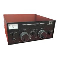
The TEN-TEC Model 4229 Antenna Tuner Kit is a user-assembled version of the TEN-TEC Model 229 tuner, designed to match the impedance of an antenna to a radio's output, thereby optimizing power transfer and minimizing standing wave ratio (SWR). This kit uses identical components to the factory-manufactured Model 229, with the primary difference being the front panel treatment. The average construction time for the kit is approximately 8 hours.

Function Description:

The 4229 Antenna Tuner is a passive device that allows for the adjustment of impedance to achieve a low SWR, typically 1:1, between a transmitter and a wide range of antennas, including balanced lines, single-wire antennas, and coaxial-fed antennas. It features a variable capacitor and a variable inductor to achieve the necessary impedance matching. The tuner also incorporates an SWR meter for monitoring forward power (FWD), reflected power (REV), and SWR, with selectable power ranges (200W and 2KW). A bypass switch allows the antenna to be connected directly to the radio, bypassing the tuning circuit.

Important Technical Specifications (derived from the manual and schematic):

  • Model: TEN-TEC Model 4229 Antenna Tuner Kit (kit version of Model 229)
  • Power Ranges: 200W and 2KW for SWR metering.
  • Antenna Connections:
    • Four coaxial antenna connectors (ANT 1, 2, 3, 4)
    • Balanced line terminals
    • Single wire terminal
    • Input coaxial connector
  • Capacitor: Variable capacitor assembly #80962, consisting of 25 semicircular rotor plates and 25 rotor spacers, and 24 rectangular stator plates with 46 stator spacers.
  • Inductor: Variable inductor assembly #81040, featuring a coil assembly with a roller contact mechanism for variable inductance.
  • SWR Board: Assembly #80859, includes components like diodes (D20, D21 - IN4148), resistors (R20, R21, R22, R23, R27), capacitors (C20, C21, C22, C23, C24, C25, C26, C27), and a toroid transformer (T20).
  • Meter Switch Board: Assembly #80958, includes push switches, thumbwheel potentiometers (R30, R31 - 10K trimpots), and resistors (R28 - 47K, R29 - 10K).
  • Power Requirement: 12 VDC for meter illumination.
  • Physical Dimensions (approximate, based on side plate size): 10" x 4-1/4" for side plates.
  • Construction Time: Approximately 8 hours.

Usage Features:

  • SWR Metering: The front panel includes a meter to display FWD, REV, and SWR, with selectable power ranges (200W/2KW). An SWR SET control allows for calibration of the SWR meter.
  • Tuning Controls: Large knobs for "CAPACITOR" (variable capacitor) and "INDUCTOR" (variable inductor) allow for precise tuning.
  • Antenna Selection: A multi-position switch (S2) on the rear panel allows selection between four coaxial antennas, balanced line, and single wire.
  • Bypass Function: A "BYPASS" switch (S1) on the front panel allows the tuner to be bypassed, connecting the antenna directly to the radio.
  • External Capacitor Connection: An "EXT CAPACITOR" terminal on the rear panel suggests the possibility of connecting an external capacitor for extended tuning range or specific applications.
  • 12 VDC Input: For powering the meter illumination.
  • Front Panel Aesthetics: The kit version features a distinct front panel treatment compared to the factory-built Model 229.
  • Clear Instructions: The manual provides "easy-to-follow instructions and construction aids" including silk-screened component designations and switch wafer terminations on circuit boards and the back panel.
  • Tool List: A comprehensive list of required and recommended tools is provided, including soldering iron, solder, screwdrivers, pliers, center punch, hammer, wire stripper, and household lubricant.
  • Mechanical Adjustments: Detailed steps are provided for adjusting the variable capacitor and inductor assemblies, including plate alignment, rotor tension, and stator plate positioning. Lubrication of bearing holes is also specified.
  • Wiring Procedures: Specific instructions are given for soldering components, cutting and dressing leads, and ensuring proper polarity for diodes and transformer leads.
  • Inspection: The manual emphasizes inspecting for "excessive solder 'blobs' or drips and wire ends that may loosen and cause shorts" and resoldering "questionable cold soldered, insufficient solder, excessive solder, etc."
  • Cleaning: Before final assembly of the front panel, users are instructed to "carefully inspect both of these panels for appearance. Clean the painted front of the aluminum panel and both sides of the plastic panel. Any smudges or grease marks (finger prints, etc.) will be locked in for the life of this unit. Use a soft cloth dry or with soap or detergent that will not attack the plastic."
  • Post-Assembly Check: Before installing the top cover, a final inspection for "obvious shorts, unsoldered connections, and see that all shafts and controls operate properly" is required.
  • Alignment: The manual includes instructions for calibrating the slide rule dial with the variable inductor.
  • Owner's Manual: The kit includes the Owner's Manual for the TEN-TEC Model 229 Antenna Tuner for testing and alignment procedures.

Ten-Tec 4229 Specifications

General IconGeneral
BrandTen-Tec
Model4229
CategoryTuner
LanguageEnglish

Related product manuals