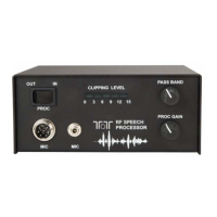
The 715 RF speech processor is installed between the microphone and the microphone jack
on your transceiver. Two inputs for microphones are provided. A conventional 8 pin
microphone connector that is wired the same as the 8 pin microphone input on the Omni-
VII and Orion II transceivers (also wired the same as 8 pin Yaesu connectors), and a second
1/8” input used for direct connection of microphones or headsets like Heil Sound, etc. The
output connector is a 1/4” stereo connector. Output cables are available for 4 pin Ten-Tec, 8
pin Ten-Tec (also used by Yaesu), 8 pin Icom, 8 pin Kenwood (also used by Elecraft).
AF clipping or compression processors found in a typical HF transceiver typically create
distortion consisting of harmonics and IMD products. An RF speech processing system
converts the input audio signal to an RF SSB signal. It is then clipped, fed through a
ceramic filter and returned to audio, effectively removing harmonic distortion that would
have been present in an AF system.
Model 715 takes the input audio signal, converts to a 455 kHz DSB signal, removes the
opposite sideband and limits distortion products with filtering before returning the
resulting signal back to audio for output to your transceiver.
Why use an RF speech processor? Several reasons, all related to signal copyability. The
increase in average power output between a non-processed and a processed signal under
marginal band conditions can be enough to make the difference between being heard and
not being heard. During DXpeditions or contests, the goal is to be heard before everyone
else or through a pileup. Maximizing average power output whether you are running
barefoot or using an external linear amplifier is a paramount consideration. Why not take
full advantage of the allowable legal maximum power output? Much of average power is
lost as high amplitude, low energy voice peaks. Increasing average power by a few dB is
like having an extra amplifier or a better antenna available than what you are currently
using.
SPECIFICATIONS:
Power requirements: 12-20 VDC. 110 VAC wall adapter provided.
Microphone Input Impedance: Max 50k ohms.
Microphone Input Sensitivity: 1 mv or greater
Polarizing Voltage: +9 VDC at input pin 2
Low Freq Response: With passband control centered, -3 dB @ 800 Hz. Max low frequency
with passband control full clockwise, -3 db at 450 Hz. Minimum with control full
counterclockwise -3 dB @ 1300 Hz. All specified without clipping. Low frequency response
will vary with the amount of clipping added.
High Frequency Response: -3 dB @ 4500 Hz.
Clipping: Max 15 dB as indicated by bargraph.
Ten-Tec, Inc., 1185 Dolly Parton Parkway, Sevierville, TN 37862 USA. www.tentec.com
Sales: (800) 833-7373 sales@tentec.com General inquiries: (865) 453-7172
 Loading...