EasyManua.ls Logo

Tenma 72-6802 User Manual

Tenma 72-6802
21 pages
To Next Page IconTo Next Page
Page #1 background imageLoading...
Page #1 background image
30MHz Dual Trace Oscilloscope
Model 72-6802
USER MANUAL
This manual contains proprietary information, which is protected by copyrights. All rights
are reserved. No part of this manual may be photocopied, reproduced or translated to
another language without prior written consent of Tenma Test Equipment.
The information in this manual was correct at the time of printing. However, Tenma
continues to improve products and reserves the rights to change specification, equipment,
and maintenance procedures at any time without notice.
Tenma Test Equipment
405 S. Pioneer Blvd. Springboro Ohio, 45036
Question and Answer IconNeed help?

Do you have a question about the Tenma 72-6802 and is the answer not in the manual?

Tenma 72-6802 Specifications

General IconGeneral
BrandTenma
Model72-6802
CategoryTest Equipment
LanguageEnglish

Summary

Safety Instructions

Safety Symbols

Symbols used in the manual and on the instrument.

General Safety Guidelines

General safety precautions and warnings for operation.

Fuse and Power Supply Safety

Fuse Safety Details

Details on fuse type, rating, and replacement for safety.

Power Supply Safety Details

Information on AC input voltage and grounding for safety.

UK Power Cord Safety Instructions

Product Overview

Product Description

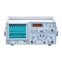
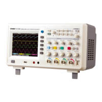
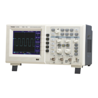
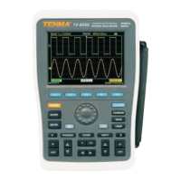
A general description of the Tenma Model 72-6802 oscilloscope.

Front Panel Layout

Front Panel Overview

General layout and description of the oscilloscope's front panel.

LCD Display Information

LCD Display

Details the information displayed on the oscilloscope's LCD screen.

Horizontal Controls

Horizontal Controls

Explains the controls for adjusting the horizontal scale and position.

Vertical Controls

Vertical Controls

Details the controls for vertical scale, position, and display modes.

Trigger Controls

Trigger Controls

Describes controls for trigger mode, level, slope, source, and TV triggering.

Trigger Settings Details

Trigger Settings Details

Specific details on trigger slope, source selection, and external trigger input.

Input Terminals

Input Terminals

Explains CH1, CH2, GND terminals and AC/GND/DC coupling.

Rear Panel Overview

Rear Panel Overview

Details the connectors and selectors on the rear panel.

Setup

Default Settings

Instructions for setting front panel controls to default states.

Setup and Probe Compensation

Setup and Probe Compensation

Step-by-step guide for initial setup and probe compensation.

Single Channel Measurement

Single Channel Measurement

Guide for performing basic measurements using one channel.

Dual Channel Measurement

Dual Channel Measurement

Instructions for performing measurements with both channels.

Waveform Operations

Waveform Addition/Subtraction

How to add or subtract waveforms from CH1 and CH2.

Frequency Measurement

Method for measuring signal frequency using the LCD or CH1 output.

X-Y Mode

X-Y Mode

Using CH1 for X-axis and CH2 for Y-axis to analyze signals.

Waveform Magnification

Waveform Magnification

How to magnify waveforms horizontally for detailed observation.

FAQ (Troubleshooting)

Probe Waveform Distortion Issues

Troubleshooting guide for distorted probe waveforms.

Trace Line Not Appearing Issues

Solutions for when the trace line is not visible on the display.

FAQ (More Issues)

Alternate Trigger Issues

Troubleshooting steps for the alternate trigger function.

Frequency Counter Not Working Issues

Reasons why the frequency counter may not function.

TV Trigger Problems

Troubleshooting for the TV-V and TV-H trigger modes.

Input Signal Not Displaying Issues

Checks for when no input signal appears on the display.

Oscilloscope Accuracy Issues

Information on achieving accurate measurements and specifications.

Appendix

Line Voltage and Fuse Replacement

Guide on selecting line voltage and replacing fuses.

Appendix (Specifications)

Specifications

Detailed technical specifications for the oscilloscope.

Appendix (Compliance)

Declaration of Conformity

Statement of compliance with EMC and Low Voltage Directives.

Related product manuals