Do you have a question about the Tenma 72-7630 and is the answer not in the manual?
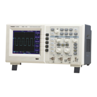
Lists the core capabilities of the oscilloscope.
Details the items provided with the oscilloscope unit.
Step-by-step guide on connecting and setting up input signals.
Procedure for adjusting probe compensation for accurate measurements.
Function to automatically configure waveform display settings.
Adjusts vertical position, scale, and channel display.
Adjusts horizontal position and time base scale.
Configures trigger level, source, coupling, mode, and slope.
Configures individual channel vertical settings like coupling and Volts/Div.
Explains AC, DC, and Ground coupling modes for signal input.
Adjusts the signal bandwidth limit for channels.
Sets the vertical scale factor in coarse or fine tune modes.
Matches probe attenuation factor to channel menu settings.
Inverts the displayed waveform by 180 degrees.
Chooses window functions like Rectangle, Hanning for FFT analysis.
Adjusts the horizontal placement of waveforms on the screen.
Adjusts time base and window width for waveform display.
Enables magnified waveform viewing with two time bases.
Triggers based on specific pulse width conditions.
Configures triggering for NTSC or PAL video signals.
Triggers based on signal rising or falling rate.
Enables triggering on two unrelated signal frequencies.
Sets waiting time before re-arming the trigger.
Selects signal components (DC, AC, reject) for trigger circuit.
Selects input channels, external, or line for triggering.
Sets trigger behavior to Auto, Normal, or Single.
Selects sampling methods like Normal, Peak Detect, Average, Envelope.
Sets the number of waveforms for averaging.
Displays CH1 vs CH2 or CH3 vs CH4 as an XY plot.
Steps for saving/recalling waveforms, setups, and bitmaps.
Indicates oscilloscope status (running/stopped) via indicator light.
Controls the visibility of the current menu on the screen.
Guides through updating the oscilloscope firmware via USB.
Details sampling modes and rates for real-time and equivalent sampling.
Specifies input coupling, impedance, probe attenuation, and voltage limits.
Covers waveform interpolation, record length, scanning range, and accuracy.
Details analogue bandwidth, rise time, A/D converter, and Volts/Div range.
Lists trigger sensitivity, level range, capability, and modes like Edge, Pulse.
Configuration for slew rate trigger conditions and range.
Settings for NTSC or PAL video signal triggering.
Specifications for the built-in frequency counter.
Details cursor modes, units, and measurement capabilities.
Lists parameters measured automatically for voltage and time.
Specifications for DC/AC voltage, resistance, and diode tests.
Instructions for safely cleaning the oscilloscope exterior and probes.
| Category | Test Equipment |
|---|---|
| Model | 72-7630 |
| Type | Digital Multimeter |
| Display | LCD |
| DC Voltage Range | 200mV to 1000V |
| DC Current Range | 200µA to 10A |
| AC Current Range | 200µA to 10A |
| Resistance Range | 200Ω to 20MΩ |
| Diode Test | Yes |
| Continuity Check | Yes |
| Power Supply | 9V Battery |
| Safety Rating | CAT II 600V |
| Display Digits | 3.5 |
| Special Features | Data Hold |
| Capacitance Range | 20nF to 200µF |