5
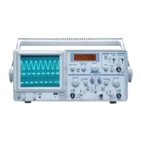
DISPLAY SETTING CONTROLS
Using the Autoset function
• Connect the signal to be measured to the signal input channel.
• Press AUTO and the oscilloscope will scan the time base and trigger mode and set
the vertical deection factor. You can manually adjust further after this process to
get the optimum display.
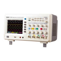
Vertical control panel
• The POSITION control centres the waveform in
the display.
• Press CH1, CH2, CH3, CH4, MATH or
REFERENCE and the screen shows the
corresponding operation menu, sign, waveform
and range status information.
• Use VOLTS/DIV (CH1, CH2, CH3, CH4) to set
the vertical gratitude factor.
• Press OFF to disable the selected channel.
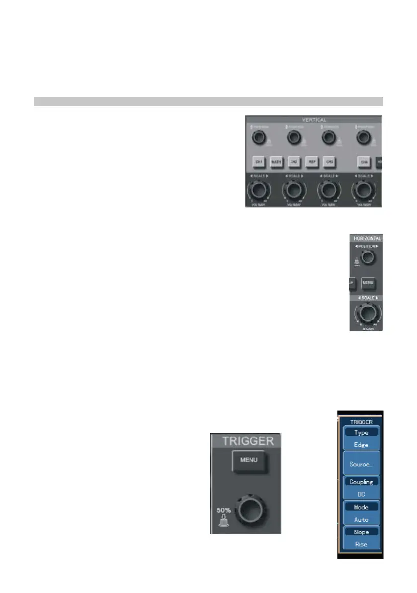
Horizontal control panel
• Horizontal position control adjusts the position of the waveform window by
adjusting the trigger shift of the signal.
• The horizontal scale adjustment changes the SEC/DIV time base range
and the current status indicator will change accordingly.
• The horizontal scanning rate range is 5ns - 50ns in steps of 1-2-5.
Note: the horizontal scanning time base range varies between models - see
table in specication section.
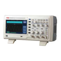
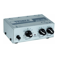
Trigger system
• The trigger level rotary control adjusts the trigger level. The display value changes
on the display as you make adjustment.
• Press MENU to select the trigger options.
• Press F1 and set EDGE TRIGGER.
• Press F2 and set SIGNAL SOURCE to CH1.
• Press F3 then F1 and set DC as
COUPLING.
• Press F4 then F1 and set MODE as
AUTO.
• Press F5 then F2 and set RISE for
SLOPE.