Do you have a question about the Tenma 72-6947 and is the answer not in the manual?
Instructions for measuring the impedance of individual speakers, including range selection.
Procedure for measuring impedance of distributed speaker systems and calculating wattage.
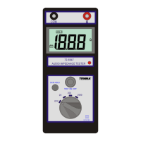
The Tenma Model 72-6947 is an audio impedance tester designed for true measurement of speaker system impedance at 1kHz. This portable, battery-operated device offers convenience for testing various sound systems, including home theater and commercial setups.
The primary function of the Tenma 72-6947 is to measure the actual impedance of speaker systems. It provides three test ranges: 20, 200, and 2000 ohms, allowing for versatility in testing different types of speakers and configurations. The device generates a 1kHz test signal to accurately determine impedance.
A key feature is its ability to measure individual speakers. For typical speakers with impedances between 2 and 16 ohms, the 20-ohm range is recommended. For special application speakers or those connected to impedance matching transformers or volume controls, which may have much higher impedances, the 200-ohm or 2000-ohm ranges can be used.
Beyond individual speakers, the tester is also designed for measuring 25V/70V distributed speaker systems, commonly found in large installations. These systems often utilize 25.2V or 70.7V transformers to simplify speaker connections and accommodate long cable runs. In such setups, speakers are typically connected in parallel, and their wattage ratings are added to determine the overall system rating. By connecting the tester to such an arrangement, the overall impedance of the system can be measured. This impedance, along with the system's voltage (e.g., 70.7V or 25.2V), can then be used with the formula E²/Z = P to calculate the total system wattage. It is crucial that this calculated total wattage does not exceed the amplifier's output rating to prevent damage.
The device incorporates a data hold function, allowing users to freeze the displayed reading for easier recording or observation. It also features a timer function for continuous, hands-free operation, with the test lasting approximately 3-5 minutes after pressing the TEST ON/OFF button.
Before operation, users are advised to ensure the system under test is not live to prevent electrical shock. The device includes an LCD display that shows the measured impedance. A low battery indication, represented by a battery symbol, alerts the user when the batteries need replacement. When the data hold function is active, the "HOLD" symbol appears on the display.
Operation involves setting the rotary switch to the appropriate range (20, 200, or 2000 ohms) based on the expected impedance of the speaker system. Once the range is selected, pressing the "TEST ON/OFF" pushbutton initiates the measurement, and the reading is displayed on the LCD. The test leads are connected to the "COM" and "Ω" terminals on the device.
The device is designed for indoor use, with an installation category of CAT. III 100V and a pollution degree of 2. It can operate at altitudes up to 2000 meters, with a maximum relative humidity of 80%, and within an ambient temperature range of 0°C to 40°C.
Maintenance of the Tenma 72-6947 primarily involves battery replacement and cleaning.
Battery Replacement: The device is powered by six 1.5V "AA" (UM-3) batteries. A low battery symbol on the display indicates when the batteries need to be replaced. To replace them, the test leads must first be disconnected from the instrument, and the power turned off. Two screws located at the bottom of the rear panel need to be removed, allowing the battery door to slide down. The old batteries are then replaced with six new "AA" type alkaline batteries. It is important not to mix different battery types or old and new batteries. After replacement, the battery door and screws are re-secured.
Cleaning and Storage: To prevent electrical shock or damage, users are warned not to allow water or excessive moisture inside the meter's case. The case can be periodically wiped with a damp cloth and a mild detergent; abrasive cleaners or solvents should not be used. For long-term storage (periods longer than 60 days), it is recommended to remove the batteries from the device and store them separately to prevent potential leakage and damage.
The meter is protected throughout by double insulation or reinforced insulation, indicated by the double square symbol. A warning symbol alerts users to the risk of electric shock, and a caution symbol directs them to refer to the manual before using the meter. A note explicitly states not to use the device on live systems.
| Type | Digital Multimeter |
|---|---|
| Continuity Buzzer | Yes |
| Data Hold | Yes |
| Auto Power Off | Yes |
| Battery | 9V |
| Power Supply | 9V Battery |
| Safety Rating | CAT III 600V |
| Measurement Functions | Voltage, Current, Resistance, Capacitance, Frequency, Temperature |
| Temperature Range | -20°C to 1000°C |
| Frequency Range | 10Hz to 10MHz |