-5-
(10 W)
(50 W)
(200W)
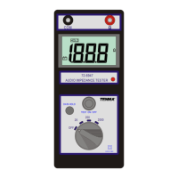
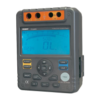
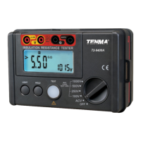
AUDIO IMPEDANCE TESTER
CAT.III 100V
OFF
72-6947
20W
200W
COM
TEST ON / OFF
2000W
HOLD
-+
DATA HOLD
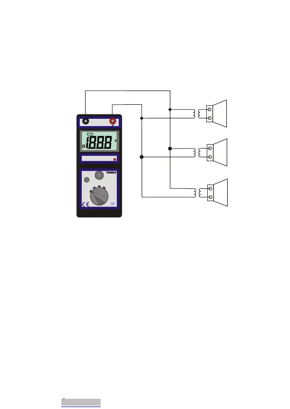
Measuring 25V/70V Distributed Speaker Systems
5. Large distributed systems typically utilize 25.2V or 70.7V transformers
(50V and 100V in Europe), to greatly ease the connection of multiple
speakers and facilitate long cable runs. These speakers are connected in
parallel, as shown, with total wattage ratings added to calculate the overall
rating of the system. Connecting this meter to a speaker arrangement
such as this will provide the overall impedance of the system.
Using the formula shown below you can calculate the wattage.
Simply put, when connected to a distributed system, take the voltage
of the system (normally 70.7V or 25.2V), squared, divided by the
impedance displayed on the meter. Your answer will be the total
system wattage. This total wattage must not exceed the wattage
output rating of the amplifier, or damage may occur.
E
— = P
Z
E = Voltage Z = Impedance P = Wattage
2
Downloaded from Arrow.com.Downloaded from Arrow.com.Downloaded from Arrow.com.Downloaded from Arrow.com.Downloaded from Arrow.com.Downloaded from Arrow.com.Downloaded from Arrow.com.