6
INSTRUMENT SETUP
Vertical system setup
• Each channel CH1, CH2, CH3 or CH4 has it’s own vertical menu. Each channel
should be set up individually.
• Press CH1 to CH4 and the system will display the operation menu for that channel.
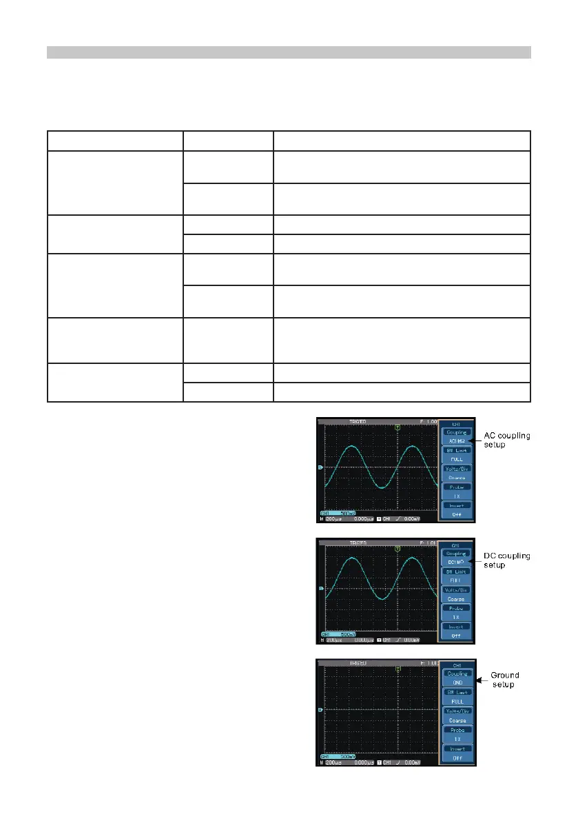
Channel coupling setup
• If for example a signal is applied to CH1
which has a sine signal that contains DC
quantities.
• Press F1 to select AC and set up as AC
coupling. Any DC quantities in the signal are
now intercepted.
• Press F1 to select DC.
• Both AC and DC quantities of the signal
being measured can now pass through.
• The waveform displays both AC and DC
quantities of the signal.
• Press F1 to select GROUND.
Both AC and DC quantities of the signal
being measured are now intercepted.
• The waveform is not displayed in this mode
but the signal remains connected
to the channel circuit.
Functions Menu Setup Notes
Coupling
AC
DC
Intercepts the DC quantities of the input signal.
Pass AC and DC quantities of input signal
GROUND
Displays reference ground level without
disconnecting the input signal
Bandwidth Limit
On Limit bandwidth to 20MHz to reduce noise display.
Off Full bandwidth
Volts / DIV
Coarse tune
Coarse tune in steps of 1-2-5 to set up the
deection factor of the vertical system.
Fine tune
Fine tune is further tuning within the coarse tune
set up to improve the vertical resolution.
Probe
1X, 10X, 100X
and 1000X
Select either value based on the probe attenuation
factor to keep the vertical deection factor reading
correct.
Invert
On Waveform invert function on.
Off Normal waveform display.
 Loading...