7
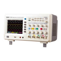
Channel bandwidth setup
• If for example a signal is applied to CH1
which is a pulse signal that contains high
frequency oscillation.
• Press CH1 to select Channel1.
• Press F2 to set the BANDWIDTH LIMIT
OFF so it is set up as full bandwidth.
• The signal being measured can now pass
through even if it contains high frequency quantities.
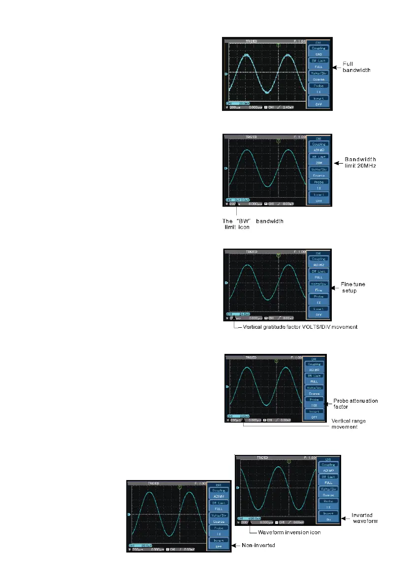
• Press F2 to set BANDWIDTH LIMIT ON
so that frequency quantities higher than
20MHz in the signal being measured will
be limited.
Probe rate setup
• To match the probe attenuation factor
setup, it is necessary to set up the probe
attenuation factor in the channel operation
menu accordingly.
• For example when the probe attenuation
factor is 10:1, set the probe attenuation
factor at 10X in the menu. This principle
applies to other values to ensure the voltage reading is correct.
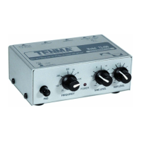
Waveform inversion setup
• The displayed signal is inverted 180 degrees
with respect to the
ground level.
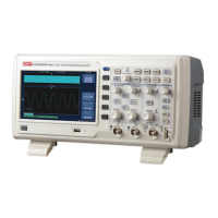
Vertical Volts/Div adjustment setup
• The VOLTS/DIV range of the vertical
deection factor can be adjusted either in
coarse or ne tune mode.
• In COARSE TUNE the VOLTS/DIV range is
2mV/div~5V/div. Tuning is in steps of 1-2-5.
• In FINE TUNE mode the deection factor
can be adjusted in smaller steps allowing
continuous adjustment within the range
2mV/div~5V/div without interruption.