EasyManua.ls Logo

Tense DS-48 User Manual

Tense DS-48
6 pages
To Next Page IconTo Next Page
Page #1 background imageLoading...
Page #1 background image
DS-48
PRESET UP/DOWN COUNTER
General Specifications:
1
ENG
2x4 Digit display, single PRESET, single OUT, up/down counter
Counts switch, proximity switch & incremental encoder input
Password protection
Selectable input frequency
Calibration constant; 0.001.....9.999
Selectable decimal point; 1. ..... 3. Digit
7 input / 9 output function options
Adss “OFFSET” to Count Value
OUT; latch or 0.1.....999.9 seconds pulse
Loads count value & OUT satus at the lastest power failure after the first power on
RESET via front panel
Displays Preset ½ values
EEPROM memory to store settings
Panel Hole Sizes
:
:
:
:
:
:
:
:
:
:
:
:
:
Display
Count Input
NPN Selection
Sensor Types
Input Frequency
Reset Input
Output
Supply Voltage
Sensor Supply
Power Consump.
Operating Temp.
Operating Altitude
44x44mm
2x4 Digit 7 Segment display
2 x (Max: 7500 Hz, 5-30V)
Connect “npn select” to “+12V” to select NPN sensor for Cp1 and Cp2.
Reset input is always PNP. For totem pole or PNP type sensor
“npn select” left unconnected.
PNP/NPN proximity switch - NPN/PNP/Totem-pole output encoder
20, 50, 2500, 7500 Hz selectable.
10ms (min) , Positive input (PNP only) (5.....30V)
Out; Relay (O-NO-NC), 250VAC, 2A, Rezistif Yük
Open Collector (NPN), 30V, 100mA max.
100...240VAC, 50-60Hz
12VDC, 50mA(max.), unregulated
< 8VA
o o
-20 C....55 C
< 2000m
Technical Specifications:
MADE IN TURKEY
Question and Answer IconNeed help?

Do you have a question about the Tense DS-48 and is the answer not in the manual?

Tense DS-48 Specifications

General IconGeneral
Counting Speed1000 notes/min
Hopper Capacity300 notes
Stacker Capacity200 notes
DisplayLCD
Power SupplyAC 100-240V, 50/60Hz
DetectionUV, MG

Summary

General Specifications

Technical Specifications

Safety and Installation

General Warnings

Use shielded cables, avoid noise, take precautions against environmental conditions, use fuse, apply safety regulations.

Connection Diagram

User Interface and Programming

Physical Dimensions

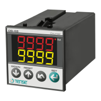
Physical dimensions of the counter unit, including front panel and depth.

Front Panel Reset Procedure

Procedure to reset the counter using the front panel button.

Programming Preset Value

Steps to set the preset value on the upper display.

Input Signal Types

Programming Parameters

Password Setting (CodE)

Enter fixed password; 162.

Output ON Duration (Out)

Out ON duration for latching enter, 0.000.

Calibration Constant (CALb)

Calibration constant.

Input Options (InPt)

Input options including pulse types.

Operating Modes Options (ConF)

Operating modes options from 0 to 8.

Decimal Point Selection (dEC.P)

Select place of decimal point.

Counting Direction (Cr.dr)

Counting direction; direct / opposite or up/down.

Input Frequency Selection (Freq)

Max. frequency for input signal. Select 20Hz for mechanical switch.

Power-on Reset Option (Pon.r)

Yes: Reset after power-on. No: Loads count value & output status from last failure.

Offset Value Setting (OFFS)

Offset Value setting for counter behavior.

Operating Modes Explained

Operating Mode 0

Counting continues up/down until RESET ON after Preset is reached.

Operating Mode 1

Counting stops until RESET ON after Preset is reached.

Operating Mode 2

Counting continues up/down until RESET ON after Preset is reached.

Operating Mode 3

Counter is reset after Preset is reached.

Operating Mode 4

Counting continues up/down after Preset is reached. Counter is reset with OUT pulse OFF.

Operating Mode 5

Counting stops after Preset is reached. Counter is reset OUT pulse OFF.

Operating Mode 6

Counter is reset after Preset is reached but display freezes until the end of OUT pulse.

Operating Mode 7

OUT is ON when counter is equal to Preset else OFF. Use SS Out for short ON time.

Operating Mode 8

OUT is ON when counter is greater or equal to Preset else OFF.