Do you have a question about the Terex Genie GS-1932m Lite and is the answer not in the manual?
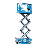
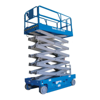
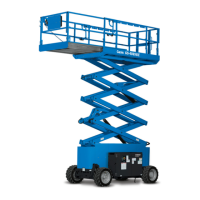
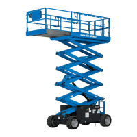
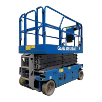
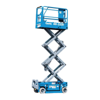
| Platform Height | 19 ft |
|---|---|
| Platform Capacity | 500 lb |
| Weight | 2, 624 lb |
| Drive Speed | 2.2 mph |
| Gradeability | 25% |
| Power Source | Electric |
| Working Height | 25 ft |
| Maximum Working Height | 25 ft |
| Capacity | 500 lb |
| Overall Width | 0.76 m |
| Platform Width | 0.76 m |
Details machine classification and design life as per ISO standards.
Specifies machine classification as Group A/Type 3 by ISO 16368.
Describes design life requirements with proper operation and maintenance.
Instructions on locating specific manuals via the Genie website.
Awareness of hazards for personnel working on or around the machine.
Awareness of hazards and safety practices in the workplace.
Details battery specifications for various Genie GS models.
Lists hydraulic fluid capacities for various Genie GS models.
Provides tire sizes and torques for various Genie GS models.
Details drive speed, function speed, and gradeability for various models.
Specifies required hydraulic oil properties and recommended fluids.
Details specifications for function pumps and manifolds for various models.
Torque specifications for Seal-Lok fittings (ORFS).
Torque specifications for JIC 37° fittings (swivel nut).
Torque specifications for SAE O-ring Boss Ports (Aluminum and Steel).
Procedure for replacing and tightening O-rings in Seal-Lok fittings.
Procedure for aligning and tightening JIC 37° fittings.
Specifies the required machine configuration for performing repair procedures.
Guidance for performing procedures, emphasizing professional service and reverse assembly.
Details the platform controls circuit board and its components.
Procedure for removing the platform joystick assembly.
Procedure for removing the platform controls alarm component.
Procedure for removing the platform emergency stop button.
Procedure to determine the machine software revision level.
Procedure for setting up machine parameters using ground controls.
Procedure for updating machine software via Bootloader or Application Mode.
Procedure for connecting to the SmartLink web service tool using a Wi-Fi router.
Procedure for operating the machine in Service Override mode.
Procedure for installing and calibrating the level sensor.
Procedure for calibrating the outrigger level sensor for GS-3232.
Procedure for removing the hydraulic tank.
Procedure for removing the hydraulic pump.
Lists function manifold components and torque specs for GS-1330m.
Lists function manifold components and torque specs for GS-1432m series.
Lists function manifold components and torque specs for GS-3232.
Lists function manifold components and torque specs for GS-4655.
Lists function manifold components and torque specs for electric drive models.
Lists function manifold components and torque specs for hydraulic drive models.
Details check valve manifold components and torque for hydraulic drive models.
Lists function manifold components and torque specs for GS-2032/2632 hydraulic models.
Details outrigger manifold components and torque for GS-3232.
Lists outrigger cylinder manifold components and torque for GS-3232.
Procedures for adjusting system and steer relief valves.
Procedure to adjust steer relief valve for hydraulic drive models.
Procedure for testing valve coils using a multimeter.
Procedure for removing the yoke assembly from the chassis.
Procedure for removing the drive motor.
Procedure for removing the steer cylinder from the machine.
Procedure for removing the steer bellcrank.
Procedure for manually releasing electric brakes.
Procedure for removing thrust washers for GS-1432m series.
Procedure for removing the drive brake on hydraulic drive models.
Lists components and torque for the hydraulic drive brake release hand pump.
Procedure for disassembling the scissor assembly for GS-1330m.
Procedure for disassembling the scissor assembly for GS-1432m.
Procedure for disassembling the scissor assembly for GS-1530/1532.
Procedure for disassembling scissor assembly for GS-1930/1932 series.
Procedure for disassembling scissor assembly for GS-1932m series.
Procedure for disassembling scissor assembly for GS-2632/2646 series.
Procedure to replace scissor arm wear pads for GS-1432m series.
Procedure to replace scissor arm wear pads for other models.
Procedure to disassemble platform height sensor assembly for GS-1432m series.
Procedure to disassemble platform height sensor assembly for other models.
Procedure for removing the lift cylinder.
Procedures for calibrating the platform overload system.
Steps for full load calibration, including battery and fluid checks.
Steps for full load calibration, including platform raising and lowering.
Procedure for no load calibration of the platform overload system.
Information on clearing the OL: PLATFORM OVERLOADED message.
Procedure for calibrating the outdoor height limiting system.
Procedure for removing the platform for GS-1432m series.
Procedure for removing the platform for all other models.
Procedure for removing the platform extension deck.
Procedure for replacing wear pads on the platform extension deck.
Describes charger features, selectable charging profiles, and status indicators.
Procedure for selecting the correct charge profile for the battery type.
Lists charger fault codes, possible causes, and solutions.
Lists charger error codes, conditions, and possible causes.
Procedure for replacing drive motor power cables on electric drive models.
Illustrates the routing and connections of drive motor power cables.
Explains the use of fault code charts and required test equipment.
Defines terms used in the diagnostics section: GSDS, ECM, GCON, PCON, OIC, DTC.
Explains alpha-numeric codes for machine status and malfunctions.
Overview of the SmartLink system indicating OIC and DTC codes.
Diagrams showing GCON ECM connector layouts for models with/without outriggers.
Details pin assignments, circuit functions, I/O type, and wire colors for GCON without outriggers.
Details pin assignments, circuit functions, I/O type, and wire colors for GCON with outriggers.
Explains codes displayed for machine operating status and malfunctions.
Explains codes indicating device or circuit malfunctions.
Steps for diagnosing and fixing HXXX and PXXX faults.
Steps for inspecting and diagnosing faults.
Lists HXXX fault codes, their messages, descriptions, causes, and failure modes.
Lists PXXX fault codes, their messages, descriptions, causes, and failure modes.
Lists UXXX fault codes, their messages, descriptions, causes, and failure modes.
Lists FXXX fault codes, their messages, descriptions, causes, and failure modes.
Lists CXXX fault codes, their messages, descriptions, causes, and failure modes.