Section 130-0010
3
SM 1534 Rev 1 3-00
Drivelines - Front and Rear Drivelines
from driveline assembly (1).
3. Place the shaft end of driveline assembly (1) in a
soft jawed vice.
4. Remove capscrews (10) and cross assembly (2)
from driveline assembly (1).
5. Repeat steps 1 to 4 for drivelines (4 & 6) and
(2 & 5, Fig. 2)
INSPECTION
1. Clean all metal parts in a suitable solvent, and dry
all parts with compressed air.
2. Inspect splines of shaft and yoke for nicks, burrs
and excessive wear. Replace if wear is excessive or
splines are nicked. Burrs may be removed with a fine
file or medium India stone.
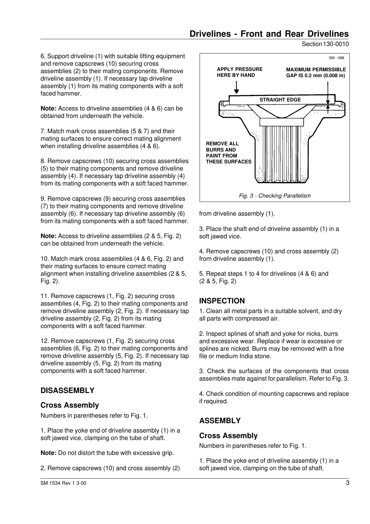
3. Check the surfaces of the components that cross
assemblies mate against for parallelism. Refer to Fig. 3.
4. Check condition of mounting capscrews and replace
if required.
ASSEMBLY
Cross Assembly
Numbers in parentheses refer to Fig. 1.
1. Place the yoke end of driveline assembly (1) in a
soft jawed vice, clamping on the tube of shaft.
6. Support driveline (1) with suitable lifting equipment
and remove capscrews (10) securing cross
assemblies (2) to their mating components. Remove
driveline assembly (1). If necessary tap driveline
assembly (1) from its mating components with a soft
faced hammer.
Note: Access to driveline assemblies (4 & 6) can be
obtained from underneath the vehicle.
7. Match mark cross assemblies (5 & 7) and their
mating surfaces to ensure correct mating alignment
when installing driveline assemblies (4 & 6).
8. Remove capscrews (10) securing cross assemblies
(5) to their mating components and remove driveline
assembly (4). If necessary tap driveline assembly (4)
from its mating components with a soft faced hammer.
9. Remove capscrews (9) securing cross assemblies
(7) to their mating components and remove driveline
assembly (6). If necessary tap driveline assembly (6)
from its mating components with a soft faced hammer.
Note: Access to driveline assemblies (2 & 5, Fig. 2)
can be obtained from underneath the vehicle.
10. Match mark cross assemblies (4 & 6, Fig. 2) and
their mating surfaces to ensure correct mating
alignment when installing driveline assemblies (2 & 5,
Fig. 2).
11. Remove capscrews (1, Fig. 2) securing cross
assemblies (4, Fig. 2) to their mating components and
remove driveline assembly (2, Fig. 2). If necessary tap
driveline assembly (2, Fig. 2) from its mating
components with a soft faced hammer.
12. Remove capscrews (1, Fig. 2) securing cross
assemblies (6, Fig. 2) to their mating components and
remove driveline assembly (5, Fig. 2). If necessary tap
driveline assembly (5, Fig. 2) from its mating
components with a soft faced hammer.
DISASSEMBLY
Cross Assembly
Numbers in parentheses refer to Fig. 1.
1. Place the yoke end of driveline assembly (1) in a
soft jawed vice, clamping on the tube of shaft.
Note: Do not distort the tube with excessive grip.
2. Remove capscrews (10) and cross assembly (2)
SM - 088
REMOVE ALL
BURRS AND
PAINT FROM
THESE SURFACES
STRAIGHT EDGE
MAXIMUM PERMISSIBLE
GAP IS 0.2 mm (0.008 in)
APPLY PRESSURE
HERE BY HAND
Fig. 3 - Checking Parallelism
Courtesy of Machine.Market
 Loading...


