5
Section 160-0020
SM 1969 4-00
Rear Axle Group - Differential Drive Head
DISASSEMBLY
Numbers in parentheses refer to Fig. 3.
Note: The following removal procedure assumes the
complete axle assembly was removed from the
vehicle.
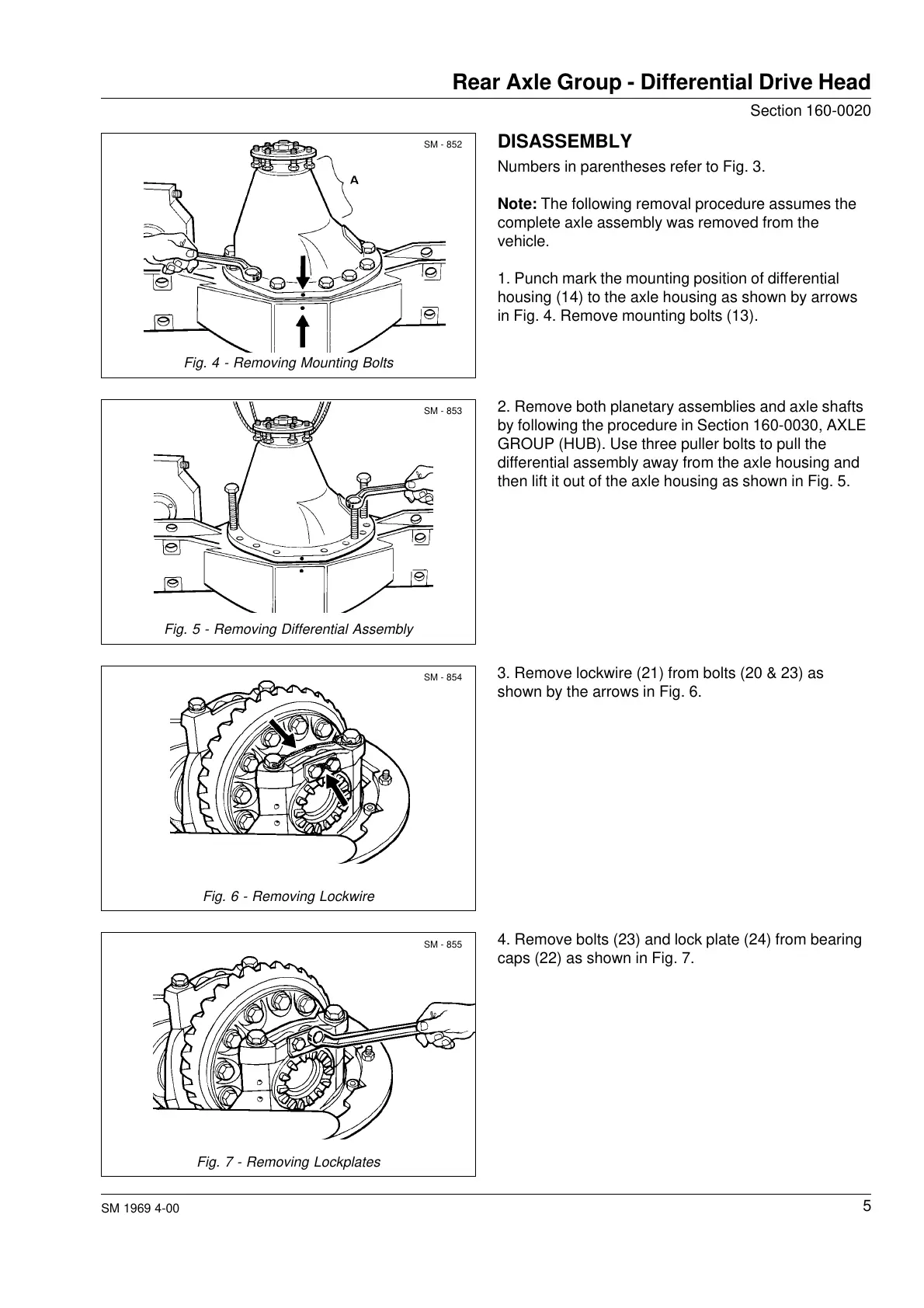
1. Punch mark the mounting position of differential
housing (14) to the axle housing as shown by arrows
in Fig. 4. Remove mounting bolts (13).
SM - 852
SM - 853
SM - 854
SM - 855
2. Remove both planetary assemblies and axle shafts
by following the procedure in Section 160-0030, AXLE
GROUP (HUB). Use three puller bolts to pull the
differential assembly away from the axle housing and
then lift it out of the axle housing as shown in Fig. 5.
Fig. 5 - Removing Differential Assembly
Fig. 6 - Removing Lockwire
4. Remove bolts (23) and lock plate (24) from bearing
caps (22) as shown in Fig. 7.
Fig. 7 - Removing Lockplates
Fig. 4 - Removing Mounting Bolts
3. Remove lockwire (21) from bolts (20 & 23) as
shown by the arrows in Fig. 6.
Courtesy of Machine.Market


 To Next Page