15
Section 160-0020
SM 1969 4-00
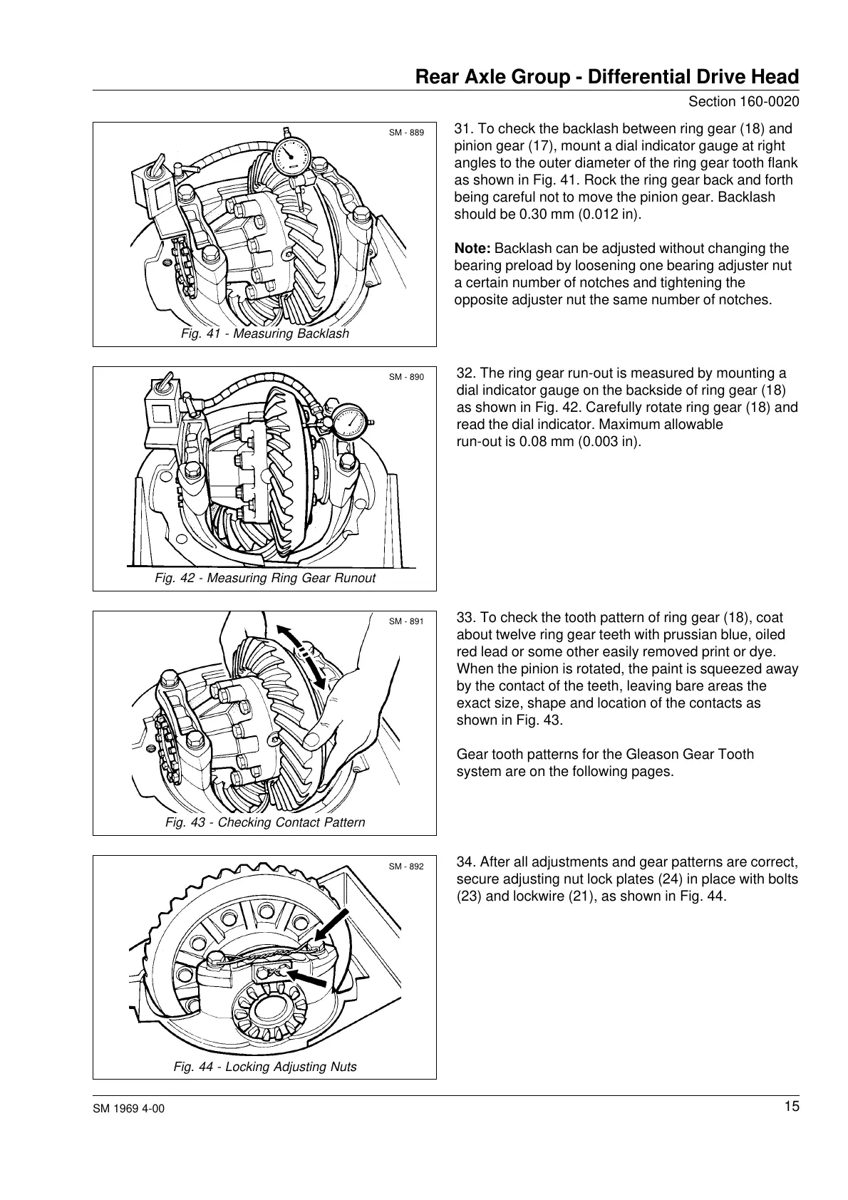
31. To check the backlash between ring gear (18) and
pinion gear (17), mount a dial indicator gauge at right
angles to the outer diameter of the ring gear tooth flank
as shown in Fig. 41. Rock the ring gear back and forth
being careful not to move the pinion gear. Backlash
should be 0.30 mm (0.012 in).
Note: Backlash can be adjusted without changing the
bearing preload by loosening one bearing adjuster nut
a certain number of notches and tightening the
opposite adjuster nut the same number of notches.
Rear Axle Group - Differential Drive Head
Fig. 41 - Measuring Backlash
Fig. 42 - Measuring Ring Gear Runout
Fig. 43 - Checking Contact Pattern
Fig. 44 - Locking Adjusting Nuts
SM - 889
SM - 890
SM - 891
SM - 892
32. The ring gear run-out is measured by mounting a
dial indicator gauge on the backside of ring gear (18)
as shown in Fig. 42. Carefully rotate ring gear (18) and
read the dial indicator. Maximum allowable
run-out is 0.08 mm (0.003 in).
33. To check the tooth pattern of ring gear (18), coat
about twelve ring gear teeth with prussian blue, oiled
red lead or some other easily removed print or dye.
When the pinion is rotated, the paint is squeezed away
by the contact of the teeth, leaving bare areas the
exact size, shape and location of the contacts as
shown in Fig. 43.
Gear tooth patterns for the Gleason Gear Tooth
system are on the following pages.
34. After all adjustments and gear patterns are correct,
secure adjusting nut lock plates (24) in place with bolts
(23) and lockwire (21), as shown in Fig. 44.
Courtesy of Machine.Market