Rear Axle Group - Axle Group (Hub)
Section 160-0030
2
SM 1968 4-00
REMOVAL AND DISASSEMBLY
Numbers in parentheses refer to Fig. 1.
Note: On dismantling, clean all parts in paraffin or
other suitable cleaning agent and place on a clean
work surface.
WARNINGS
To prevent personal injury and property
damage, be sure wheel blocks, blocking
materials and lifting equipment are properly
secured and of adequate capacity to do the job
safely.
To prevent personal injury and property
damage, the procedure for removing tyre and
rim assembly described in Section 160-0050,
WHEEL, RIM AND TYRE, must be strictly
followed.
When necessary to drive out components
during disassembly, be sure to use a soft drift
to prevent property damage and personal
injury.
1. Before attempting to remove the road wheels, drive
the vehicle onto a level, solid concrete floor,
preferably after a short run to warm the oil.
2. Apply the parking brake and switch off the engine.
3. Block the appropriate road wheels, place the
steering lock bar in the 'Locked' position and the
battery master switch in the 'Off' position.
4. Whilst road wheels are still on the ground, loosen
wheel nuts (12).
5. Jack up the axle and support with suitably placed
stands or timbers.
6. Support tyre and rim assembly with a suitable sling
and lifting device. Remove wheel nuts (12) and
remove tyre and rim assembly from the machine.
Remove opposite road wheel in the same way.
7. Place suitable containers under the differential and
both hubs (10). Remove differential drain plug and
drain oil from the differential.
8. Rotate hubs (10) until plug screws (24) are at their
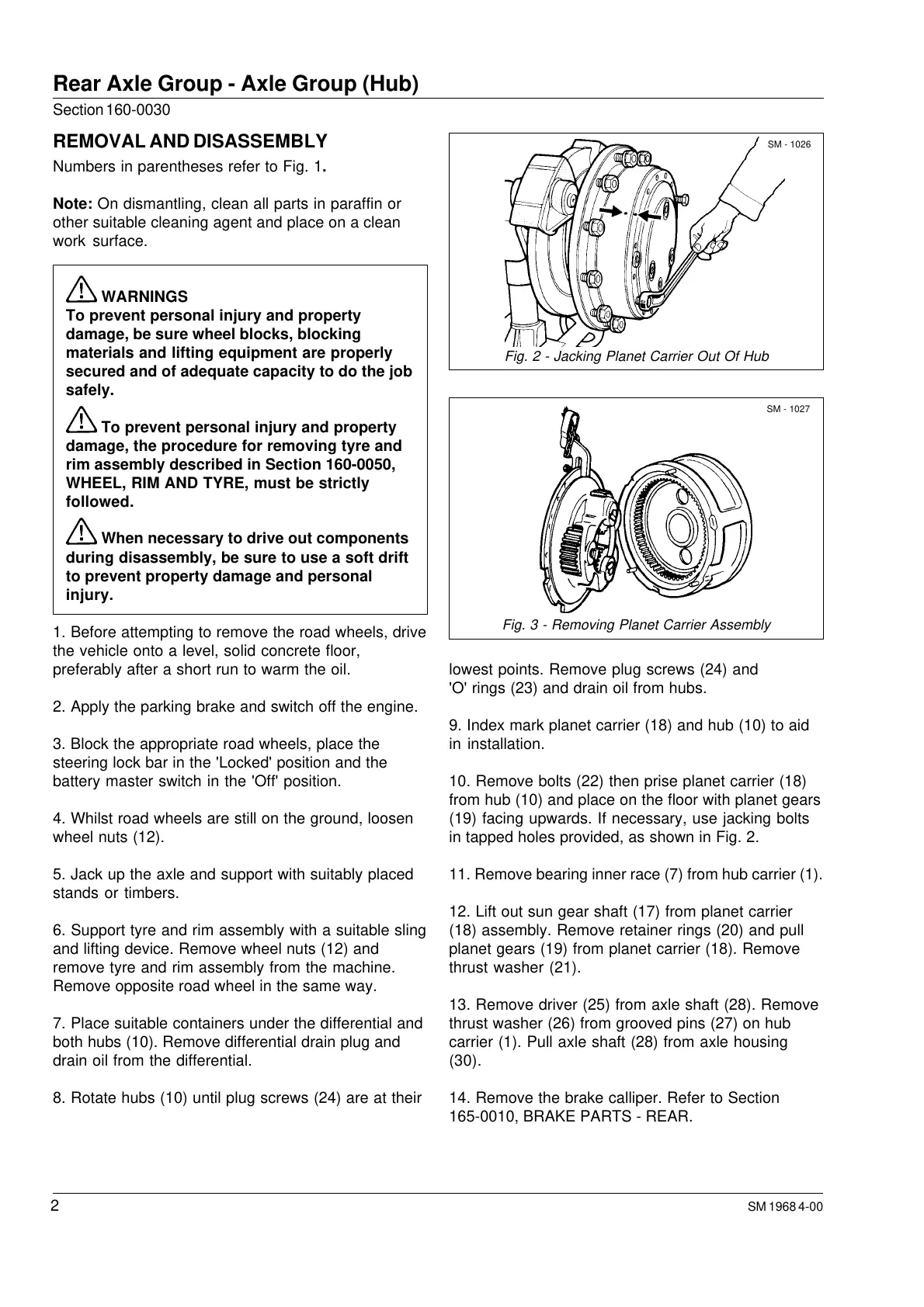
Fig. 2 - Jacking Planet Carrier Out Of Hub
Fig. 3 - Removing Planet Carrier Assembly
SM - 1026
SM - 1027
lowest points. Remove plug screws (24) and
'O' rings (23) and drain oil from hubs.
9. Index mark planet carrier (18) and hub (10) to aid
in installation.
10. Remove bolts (22) then prise planet carrier (18)
from hub (10) and place on the floor with planet gears
(19) facing upwards. If necessary, use jacking bolts
in tapped holes provided, as shown in Fig. 2.
11. Remove bearing inner race (7) from hub carrier (1).
12. Lift out sun gear shaft (17) from planet carrier
(18) assembly. Remove retainer rings (20) and pull
planet gears (19) from planet carrier (18). Remove
thrust washer (21).
13. Remove driver (25) from axle shaft (28). Remove
thrust washer (26) from grooved pins (27) on hub
carrier (1). Pull axle shaft (28) from axle housing
(30).
14. Remove the brake calliper. Refer to Section
165-0010, BRAKE PARTS - REAR.
Courtesy of Machine.Market
 Loading...


