SM 1970 4-00
Section 160-0050
1
REAR AXLE GROUP - Wheel Rim and Tyre
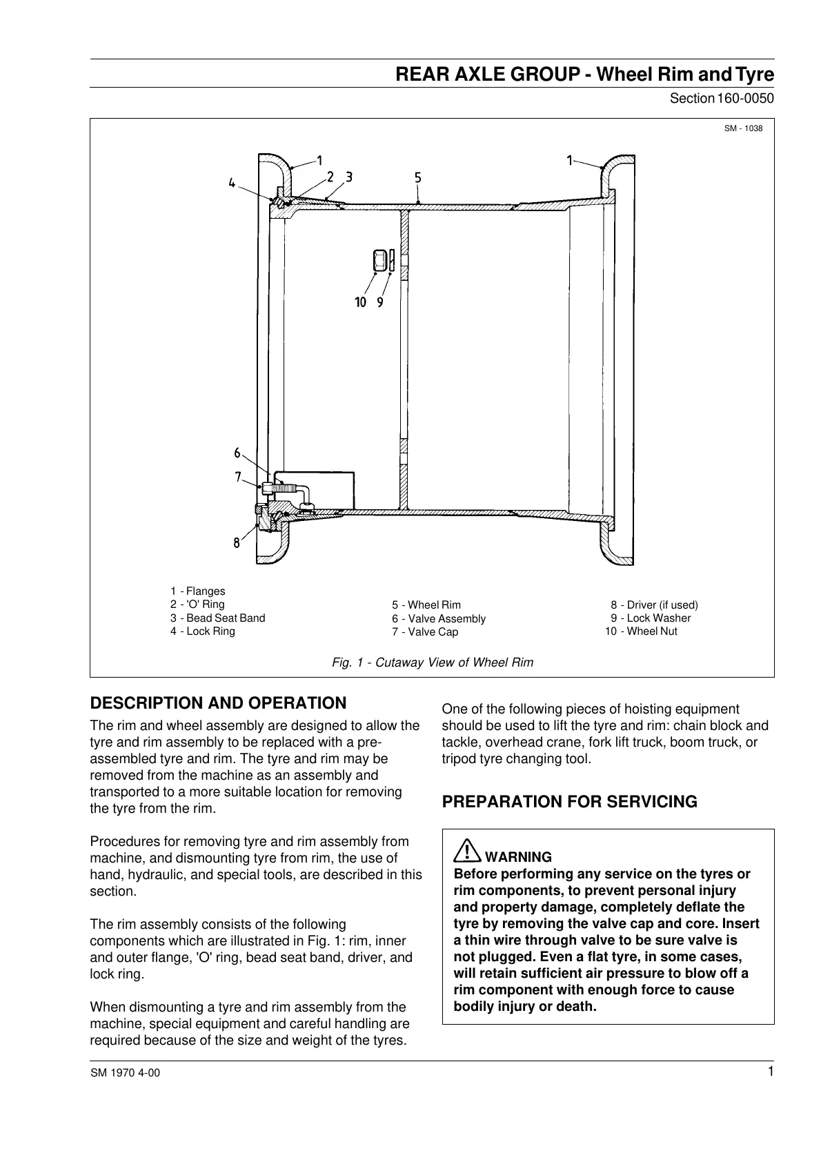
1 - Flanges
2 - 'O' Ring
3 - Bead Seat Band
4 - Lock Ring
8 - Driver (if used)
9 - Lock Washer
10 - Wheel Nut
5 - Wheel Rim
6 - Valve Assembly
7 - Valve Cap
Fig. 1 - Cutaway View of Wheel Rim
DESCRIPTION AND OPERATION
The rim and wheel assembly are designed to allow the
tyre and rim assembly to be replaced with a pre-
assembled tyre and rim. The tyre and rim may be
removed from the machine as an assembly and
transported to a more suitable location for removing
the tyre from the rim.
Procedures for removing tyre and rim assembly from
machine, and dismounting tyre from rim, the use of
hand, hydraulic, and special tools, are described in this
section.
The rim assembly consists of the following
components which are illustrated in Fig. 1: rim, inner
and outer flange, 'O' ring, bead seat band, driver, and
lock ring.
When dismounting a tyre and rim assembly from the
machine, special equipment and careful handling are
required because of the size and weight of the tyres.
One of the following pieces of hoisting equipment
should be used to lift the tyre and rim: chain block and
tackle, overhead crane, fork lift truck, boom truck, or
tripod tyre changing tool.
PREPARATION FOR SERVICING
WARNING
Before performing any service on the tyres or
rim components, to prevent personal injury
and property damage, completely deflate the
tyre by removing the valve cap and core. Insert
a thin wire through valve to be sure valve is
not plugged. Even a flat tyre, in some cases,
will retain sufficient air pressure to blow off a
rim component with enough force to cause
bodily injury or death.
SM - 1038
Courtesy of Machine.Market