SM 1962 4-00
2
Brake Parts - Brake Parts - Rear
Section 165-0010
SM - 049
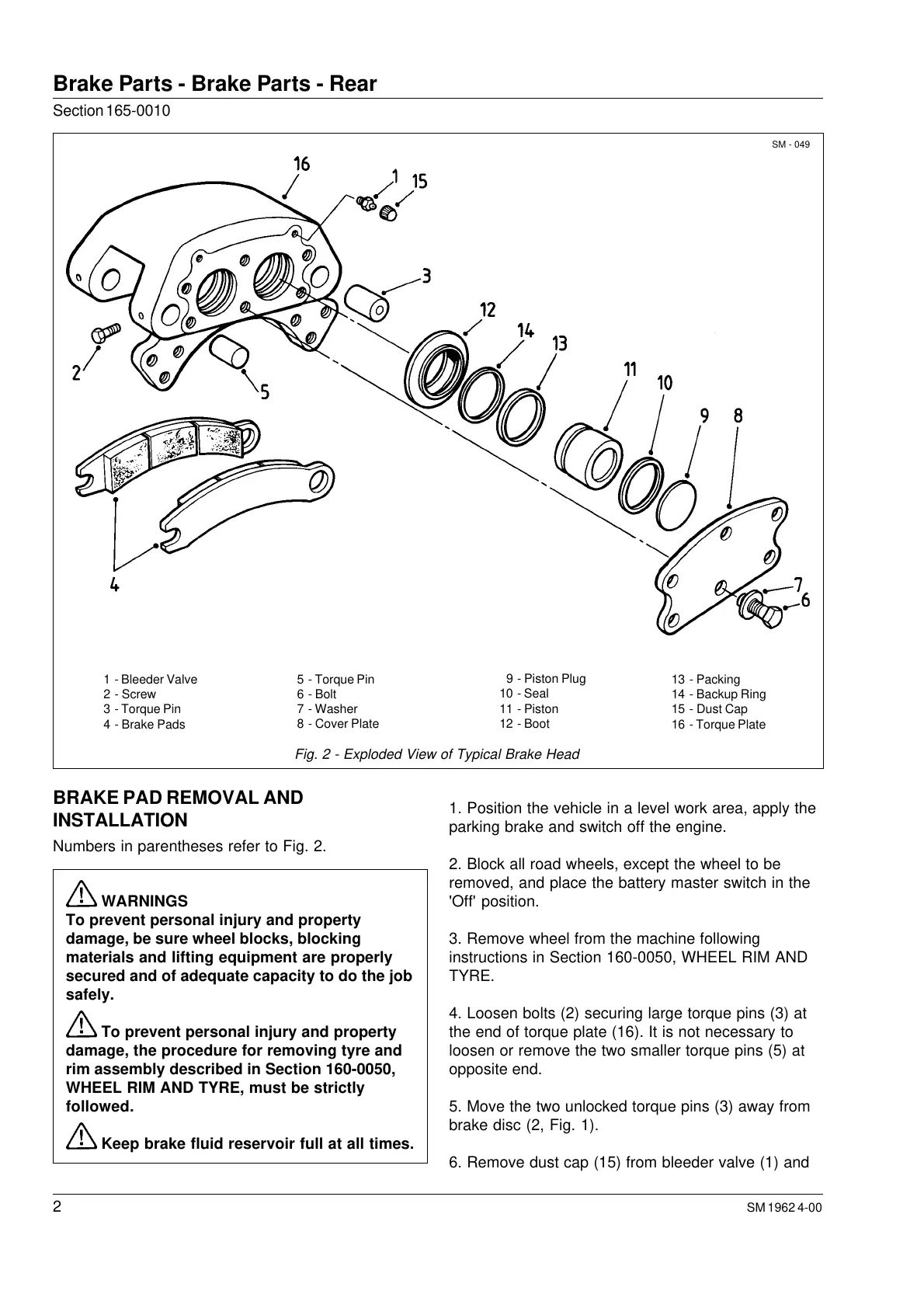
Fig. 2 - Exploded View of Typical Brake Head
1 - Bleeder Valve
2 - Screw
3 - Torque Pin
4 - Brake Pads
5 - Torque Pin
6 - Bolt
7 - Washer
8 - Cover Plate
9 - Piston Plug
10 - Seal
11 - Piston
12 - Boot
13 - Packing
14 - Backup Ring
15 - Dust Cap
16 - Torque Plate
BRAKE PAD REMOVAL AND
INSTALLATION
Numbers in parentheses refer to Fig. 2.
WARNINGS
To prevent personal injury and property
damage, be sure wheel blocks, blocking
materials and lifting equipment are properly
secured and of adequate capacity to do the job
safely.
To prevent personal injury and property
damage, the procedure for removing tyre and
rim assembly described in Section 160-0050,
WHEEL RIM AND TYRE, must be strictly
followed.
Keep brake fluid reservoir full at all times.
1. Position the vehicle in a level work area, apply the
parking brake and switch off the engine.
2. Block all road wheels, except the wheel to be
removed, and place the battery master switch in the
'Off' position.
3. Remove wheel from the machine following
instructions in Section 160-0050, WHEEL RIM AND
TYRE.
4. Loosen bolts (2) securing large torque pins (3) at
the end of torque plate (16). It is not necessary to
loosen or remove the two smaller torque pins (5) at
opposite end.
5. Move the two unlocked torque pins (3) away from
brake disc (2, Fig. 1).
6. Remove dust cap (15) from bleeder valve (1) and
Courtesy of Machine.Market
 Loading...


