Section 180-0020
1
SM 1979 4-00
SUSPENSION SYSTEM - Front Suspension
SM - 2485
DESCRIPTION
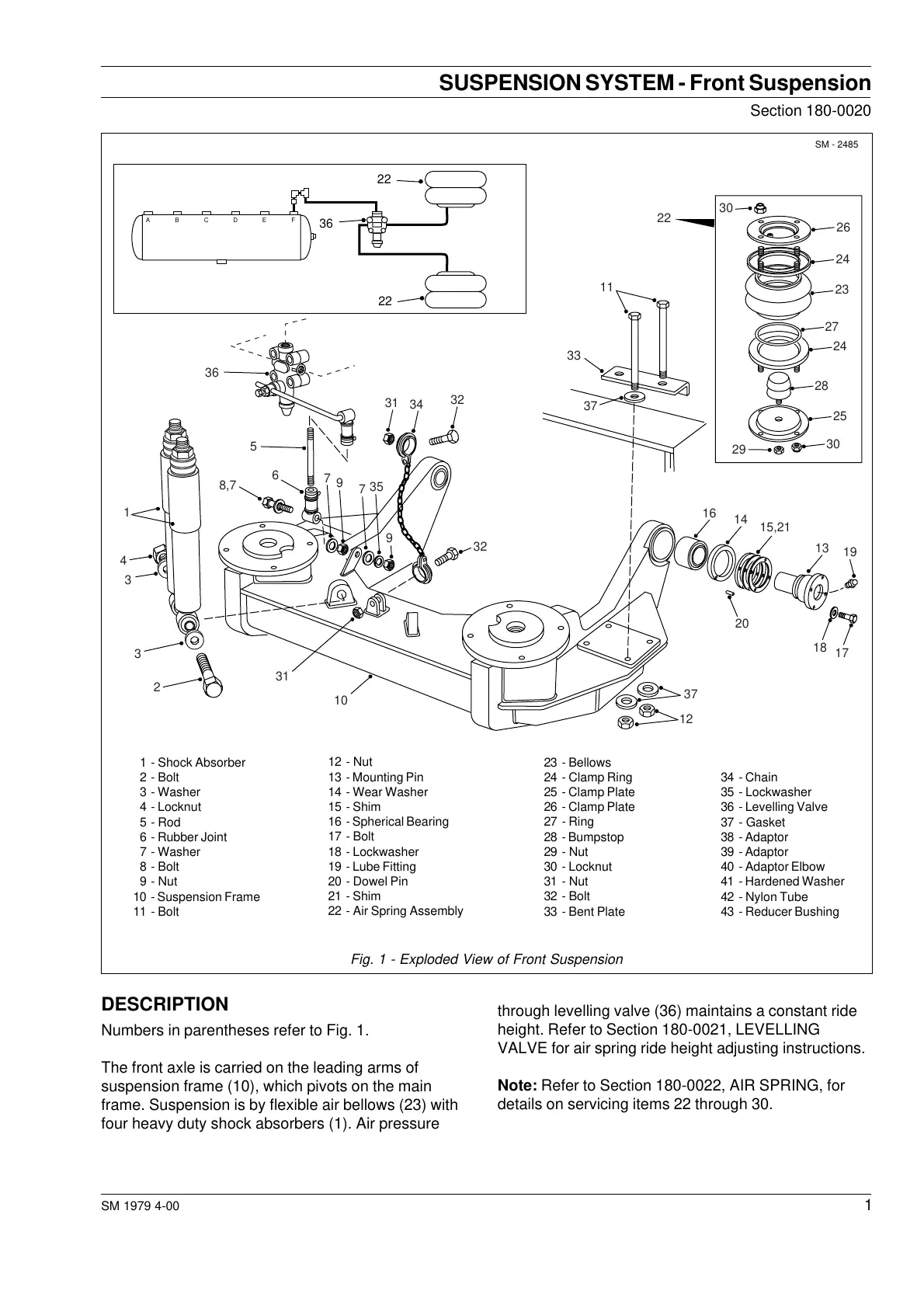
Numbers in parentheses refer to Fig. 1.
The front axle is carried on the leading arms of
suspension frame (10), which pivots on the main
frame. Suspension is by flexible air bellows (23) with
four heavy duty shock absorbers (1). Air pressure
through levelling valve (36) maintains a constant ride
height. Refer to Section 180-0021, LEVELLING
VALVE for air spring ride height adjusting instructions.
Note: Refer to Section 180-0022, AIR SPRING, for
details on servicing items 22 through 30.
Fig. 1 - Exploded View of Front Suspension
34 - Chain
35 - Lockwasher
36 - Levelling Valve
37 - Gasket
38 - Adaptor
39 - Adaptor
40 - Adaptor Elbow
41 - Hardened Washer
42 - Nylon Tube
43 - Reducer Bushing
1 - Shock Absorber
2 - Bolt
3 - Washer
4 - Locknut
5 - Rod
6 - Rubber Joint
7 - Washer
8 - Bolt
9 - Nut
10 - Suspension Frame
11 - Bolt
12 - Nut
13 - Mounting Pin
14 - Wear Washer
15 - Shim
16 - Spherical Bearing
17 - Bolt
18 - Lockwasher
19 - Lube Fitting
20 - Dowel Pin
21 - Shim
22 - Air Spring Assembly
23 - Bellows
24 - Clamp Ring
25 - Clamp Plate
26 - Clamp Plate
27 - Ring
28 - Bumpstop
29 - Nut
30 - Locknut
31 - Nut
32 - Bolt
33 - Bent Plate
ABCDEF
36
1
4
3
3
2
10
31
8,7
6
5
31
34
32
32
7
9
7
35
9
12
37
20
18
17
16
14
15,21
13
19
37
33
11
22
30
26
24
23
24
27
28
25
29
30
36
22
22
Courtesy of Machine.Market