SM 1956 4-00
1
Section 230-0130
SM - 2468
1 - Cylinder Body
2 - Piston Rod
3 - End Cap
4 - Cushion Sleeve
5 - Circlip
6 - Rod Seal
7 - Wiper
8 - 'O' Ring
9 - 'O' Ring
10 - Lock Ring
11 - Cushion Spear
12 - Piston
13 - Piston Seal
14 - Wear Ring
15 - Grub Screw
16 - 'O' Ring
17 - Back Up Ring
18 - Cushion Sleeve
19 - Circlip
20 - Spherical Bearing
21 - Circlip
22 - Nylon Ring
23 - Lube Fitting
24 - Upper Pin
25 - Spacer
26 - Bolt
27 - Lockwasher
28 - Washer
29 - Lower Pin
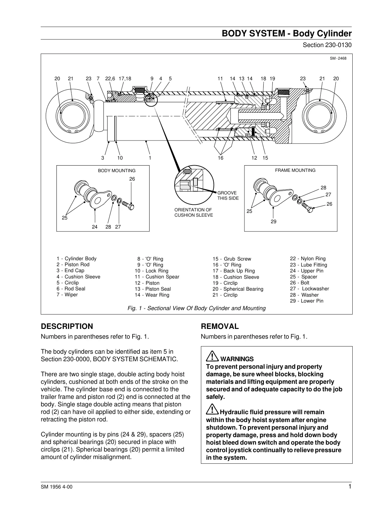
Fig. 1 - Sectional View Of Body Cylinder and Mounting
DESCRIPTION
Numbers in parentheses refer to Fig. 1.
The body cylinders can be identified as item 5 in
Section 230-0000, BODY SYSTEM SCHEMATIC.
There are two single stage, double acting body hoist
cylinders, cushioned at both ends of the stroke on the
vehicle. The cylinder base end is connected to the
trailer frame and piston rod (2) end is connected at the
body. Single stage double acting means that piston
rod (2) can have oil applied to either side, extending or
retracting the piston rod.
Cylinder mounting is by pins (24 & 29), spacers (25)
and spherical bearings (20) secured in place with
circlips (21). Spherical bearings (20) permit a limited
amount of cylinder misalignment.
REMOVAL
Numbers in parentheses refer to Fig. 1.
WARNINGS
To prevent personal injury and property
damage, be sure wheel blocks, blocking
materials and lifting equipment are properly
secured and of adequate capacity to do the job
safely.
Hydraulic fluid pressure will remain
within the body hoist system after engine
shutdown. To prevent personal injury and
property damage, press and hold down body
hoist bleed down switch and operate the body
control joystick continually to relieve pressure
in the system.
BODY SYSTEM - Body Cylinder
FRAME MOUNTING
28
27
26
25
29
BODY MOUNTING
ORIENTATION OF
CUSHION SLEEVE
GROOVE
THIS SIDE
26
20
3 10 1 16 15
21
12
23 7 22,6 17,18 9 11 1314 14 23 21 2018 194 5
2824 27
25
Courtesy of Machine.Market
 Loading...


