Section 250-0000
1
SM 1982 4-00
BRAKING SYSTEM - Hydraulic Braking System Schematic
SM - 2491
DESCRIPTION
Numbers in parentheses refer to Fig. 1.
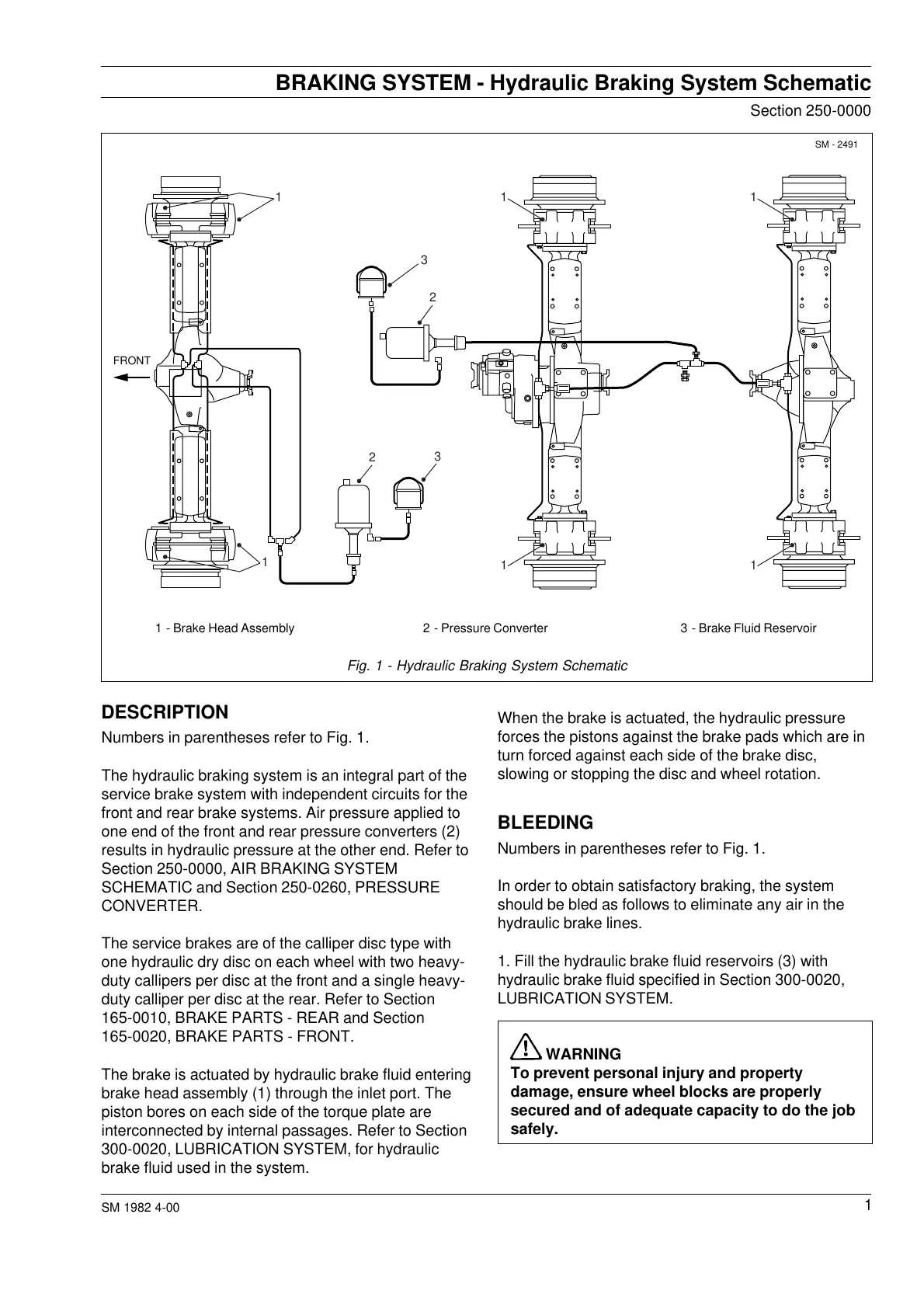
The hydraulic braking system is an integral part of the
service brake system with independent circuits for the
front and rear brake systems. Air pressure applied to
one end of the front and rear pressure converters (2)
results in hydraulic pressure at the other end. Refer to
Section 250-0000, AIR BRAKING SYSTEM
SCHEMATIC and Section 250-0260, PRESSURE
CONVERTER.
The service brakes are of the calliper disc type with
one hydraulic dry disc on each wheel with two heavy-
duty callipers per disc at the front and a single heavy-
duty calliper per disc at the rear. Refer to Section
165-0010, BRAKE PARTS - REAR and Section
165-0020, BRAKE PARTS - FRONT.
The brake is actuated by hydraulic brake fluid entering
brake head assembly (1) through the inlet port. The
piston bores on each side of the torque plate are
interconnected by internal passages. Refer to Section
300-0020, LUBRICATION SYSTEM, for hydraulic
brake fluid used in the system.
When the brake is actuated, the hydraulic pressure
forces the pistons against the brake pads which are in
turn forced against each side of the brake disc,
slowing or stopping the disc and wheel rotation.
BLEEDING
Numbers in parentheses refer to Fig. 1.
In order to obtain satisfactory braking, the system
should be bled as follows to eliminate any air in the
hydraulic brake lines.
1. Fill the hydraulic brake fluid reservoirs (3) with
hydraulic brake fluid specified in Section 300-0020,
LUBRICATION SYSTEM.
WARNING
To prevent personal injury and property
damage, ensure wheel blocks are properly
secured and of adequate capacity to do the job
safely.
1 - Brake Head Assembly 2 - Pressure Converter 3 - Brake Fluid Reservoir
Fig. 1 - Hydraulic Braking System Schematic
FRONT
1
1
1
2
2
3
3
1
11
Courtesy of Machine.Market