Section 250-0070
SM 1939 4-00
1
BRAKING SYSTEM - Treadle Valve
SM - 2368
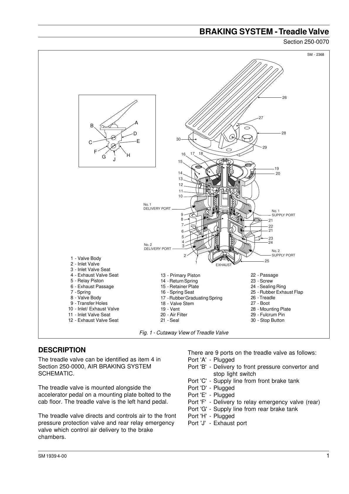
There are 9 ports on the treadle valve as follows:
Port 'A' - Plugged
Port 'B' - Delivery to front pressure convertor and
stop light switch
Port 'C' - Supply line from front brake tank
Port 'D' - Plugged
Port 'E' - Plugged
Port 'F' - Delivery to relay emergency valve (rear)
Port 'G' - Supply line from rear brake tank
Port 'H' - Plugged
Port 'J' - Exhaust port
DESCRIPTION
The treadle valve can be identified as item 4 in
Section 250-0000, AIR BRAKING SYSTEM
SCHEMATIC.
The treadle valve is mounted alongside the
accelerator pedal on a mounting plate bolted to the
cab floor. The treadle valve is the left hand pedal.
The treadle valve directs and controls air to the front
pressure protection valve and rear relay emergency
valve which control air delivery to the brake
chambers.
Fig. 1 - Cutaway View of Treadle Valve
C
G
J
F
B
H
D
E
A
26
27
28
29
30
1817
16
15
14
13
12
11
10
9
8
7
6
5
4
3
2
1
25
24
23
22
20
19
21
21
No. 1
SUPPLY PORT
No. 2
SUPPLY PORT
No. 1
DELIVERY PORT
No. 2
DELIVERY PORT
EXHAUST
22 - Passage
23 - Screw
24 - Sealing Ring
25 - Rubber Exhaust Flap
26 - Treadle
27 - Boot
28 - Mounting Plate
29 - Fulcrum Pin
30 - Stop Button
13 - Primary Piston
14 - Return Spring
15 - Retainer Plate
16 - Spring Seat
17 - Rubber Graduating Spring
18 - Valve Stem
19 - Vent
20 - Air Filter
21 - Seal
1 - Valve Body
2 - Inlet Valve
3 - Inlet Valve Seat
4 - Exhaust Valve Seat
5 - Relay Piston
6 - Exhaust Passage
7 - Spring
8 - Valve Body
9 - Transfer Holes
10 - Inlet/ Exhaust Valve
11 - Inlet Valve Seat
12 - Exhaust Valve Seat
Courtesy of Machine.Market


 To Next Page