Section 250-0190
SM 1940 4-00
1
BRAKING SYSTEM - Park/Emergency Control Valve
SM - 1947
DESCRIPTION
Note: Refer to Fig. 2 for port identification.
The park/emergency control valve can be identified as
item 8 in Section 250-0000, AIR BRAKING SYSTEM
SCHEMATIC.
The park/emergency control valve is mounted on the
right hand side dash panel in the operators compartment.
There are 4 ports on the park/emergency control valve
as follows:
Port 'A' - Supply to parking brake actuator
Port 'B' - Supply from front brake air tank via pressure
protection valve (port '23')
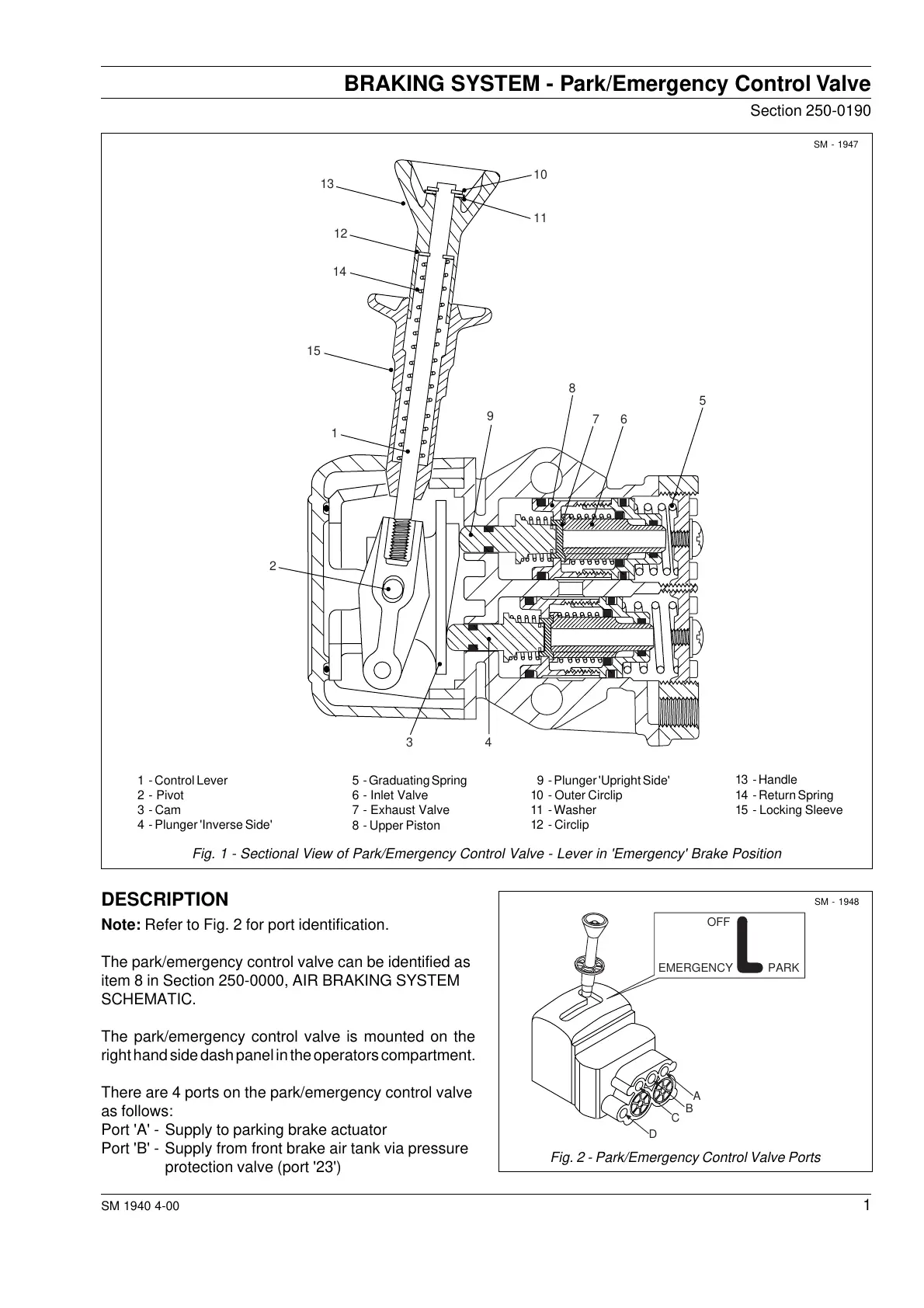
Fig. 1 - Sectional View of Park/Emergency Control Valve - Lever in 'Emergency' Brake Position
13 - Handle
14 - Return Spring
15 - Locking Sleeve
9 - Plunger 'Upright Side'
10 - Outer Circlip
11 - Washer
12 - Circlip
5 - Graduating Spring
6 - Inlet Valve
7 - Exhaust Valve
8 - Upper Piston
1 - Control Lever
2 - Pivot
3 - Cam
4 - Plunger 'Inverse Side'
SM - 1948
Fig. 2 - Park/Emergency Control Valve Ports
10
11
13
12
14
15
1
2
34
5
67
8
9
A
B
C
D
OFF
EMERGENCY PARK
Courtesy of Machine.Market

 Loading...


