Section 250-0280
SM 1945 4-00
1
BRAKING SYSTEM - Relay Emergency Valve
Fig. 2 - Operational View of Relay Emergency Valve
1 - Piston
2 - Piston
3 - Chamber A
4 - Inlet/Exhaust Valve
5 - Spring
6 - Inlet Seat
7 - Exhaust Seat
8 - Chamber B
9 - Chamber C
SM - 2456DESCRIPTION
The relay emergency valve can be identified as
item 11 in Section 250-0000, AIR BRAKING SYSTEM
SCHEMATIC.
The relay emergency valve speeds the application and
release of air pressure to and from the rear pressure
converter. The relay emergency valve is also used as
a means of preventing the force from the spring brake
and service diaphragm being applied to the foundation
brake at the same time.
OPERATION
Numbers in parentheses refer to Fig. 2.
Pressure from the park/emergency control valve is
supplied via port '42' to chamber 'C' where it acts upon
piston (1). Under the action of the pressure in chamber
'C', piston (1) moves down and contacts the back of
piston (2); they then move down together and close
the exhaust seat (7). The application of further
pressure causes pistons (1 & 2) to move the inlet/
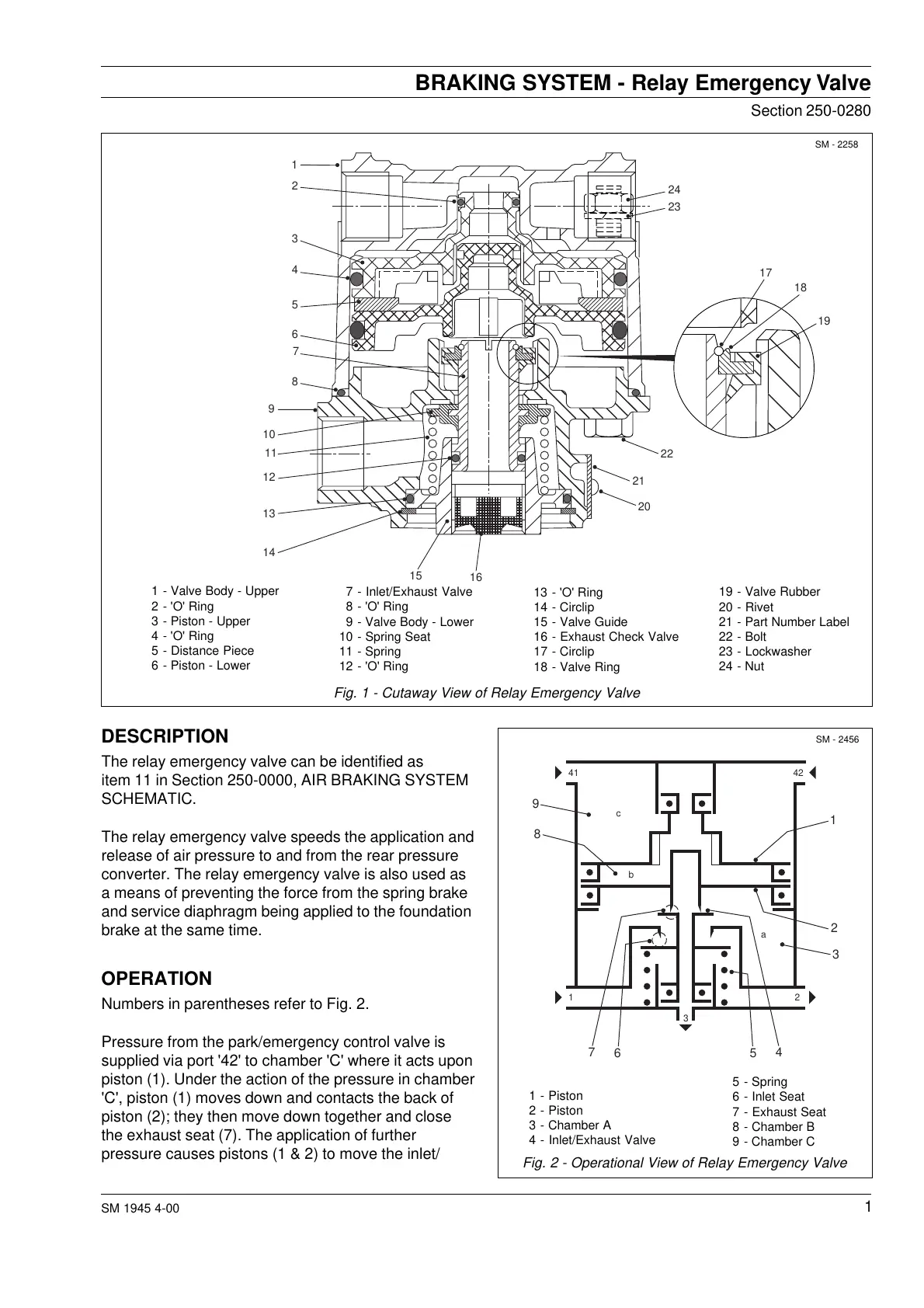
Fig. 1 - Cutaway View of Relay Emergency Valve
1 - Valve Body - Upper
2 - 'O' Ring
3 - Piston - Upper
4 - 'O' Ring
5 - Distance Piece
6 - Piston - Lower
7 - Inlet/Exhaust Valve
8 - 'O' Ring
9 - Valve Body - Lower
10 - Spring Seat
11 - Spring
12 - 'O' Ring
SM - 2258
13 - 'O' Ring
14 - Circlip
15 - Valve Guide
16 - Exhaust Check Valve
17 - Circlip
18 - Valve Ring
19 - Valve Rubber
20 - Rivet
21 - Part Number Label
22 - Bolt
23 - Lockwasher
24 - Nut
1
2
3
4
5
6
7
8
9
10
11
12
13
14
15
16
24
23
17
18
19
22
21
20
9
8
7
65
4
3
2
1
41 42
1
3
2
a
b
c
Courtesy of Machine.Market
 Loading...


