Section 100-0020
3
SM 1988 Rev 1 11-00
Chassis - Articulation and Oscillation Pivot
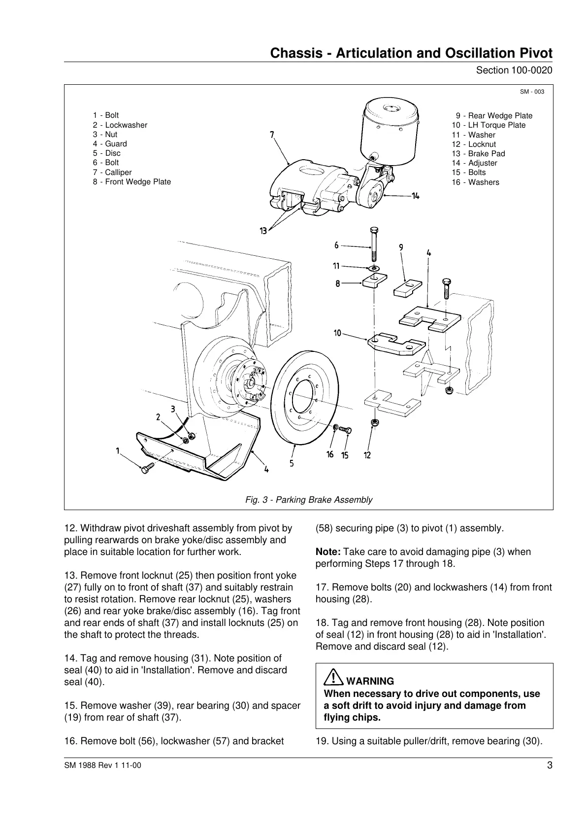
1 - Bolt
2 - Lockwasher
3 - Nut
4 - Guard
5 - Disc
6 - Bolt
7 - Calliper
8 - Front Wedge Plate
9 - Rear Wedge Plate
10 - LH Torque Plate
11 - Washer
12 - Locknut
13 - Brake Pad
14 - Adjuster
15 - Bolts
16 - Washers
SM - 003
Fig. 3 - Parking Brake Assembly
12. Withdraw pivot driveshaft assembly from pivot by
pulling rearwards on brake yoke/disc assembly and
place in suitable location for further work.
13. Remove front locknut (25) then position front yoke
(27) fully on to front of shaft (37) and suitably restrain
to resist rotation. Remove rear locknut (25), washers
(26) and rear yoke brake/disc assembly (16). Tag front
and rear ends of shaft (37) and install locknuts (25) on
the shaft to protect the threads.
14. Tag and remove housing (31). Note position of
seal (40) to aid in 'Installation'. Remove and discard
seal (40).
15. Remove washer (39), rear bearing (30) and spacer
(19) from rear of shaft (37).
16. Remove bolt (56), lockwasher (57) and bracket
(58) securing pipe (3) to pivot (1) assembly.
Note: Take care to avoid damaging pipe (3) when
performing Steps 17 through 18.
17. Remove bolts (20) and lockwashers (14) from front
housing (28).
18. Tag and remove front housing (28). Note position
of seal (12) in front housing (28) to aid in 'Installation'.
Remove and discard seal (12).
WARNING
When necessary to drive out components, use
a soft drift to avoid injury and damage from
flying chips.
19. Using a suitable puller/drift, remove bearing (30).
Courtesy of Machine.Market


 To Next Page