Section 120-0010
5
SM 1470 REV 2 6-00
WKRETARDER
INPUT
OUTPUT OUTPUT
DIFFERENTIALENGAGEMENT AND DISENGAGEMENT
DIFFERENTIAL LOCK
PUMP
1st POWER TAKE-OFF
2nd POWER TAKE-OFF
31
14
6
39
CONVERTER
KV K1
KR K2
K4 K3
D
E
F
J
H
K
G
C
B
A
56
60
55
66
67 65
51
57
53
58
52
63
SM - 1824
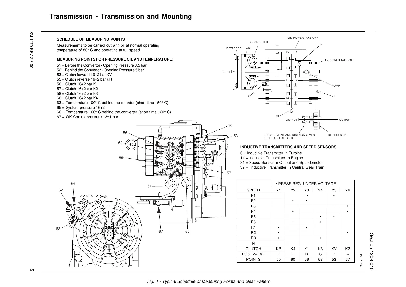
SCHEDULE OF MEASURING POINTS
Measurements to be carried out with oil at normal operating
temperature of 80° C and operating at full speed.
MEASURING POINTS FOR PRESSURE OIL AND TEMPERATURE:
51 = Before the Convertor - Opening Pressure 8.5 bar
52 = Behind the Convertor - Opening Pressure 5 bar
53 = Clutch forward 16+2 bar KV
55 = Clutch reverse 16+2 bar KR
56 = Clutch 16+2 bar K1
57 = Clutch 16+2 bar K2
58 = Clutch 16+2 bar K3
60 = Clutch 16+2 bar K4
63 = Temperature 100° C behind the retarder (short time 150° C)
65 = System pressure 16+2
66 = Temperature 100° C behind the converter (short time 120° C)
67 = WK-Control pressure 13±1 bar
• PRESS REG. UNDER VOLTAGE
SPEED Y1 Y2 Y3 Y4 Y5 Y6
F1 • •
F2 • •
F3 • •
F4 • •
F5 • •
F6 • •
R1 • •
R2 • •
R3 • •
N
CLUTCH KR K4 K1 K3 KV K2
POS. VALVE F E D C B A
POINTS 55 60 56 58 53 57
INDUCTIVE TRANSMITTERS AND SPEED SENSORS
6 = Inductive Transmitter n Turbine
14 = Inductive Transmitter n Engine
31 = Speed Sensor n Output and Speedometer
39 = Inductive Transmitter n Central Gear Train
Transmission - Transmission and Mounting
Fig. 4 - Typical Schedule of Measuring Points and Gear Pattern
Courtesy of Machine.Market