Section 120-0010
23
SM 1965 4-00
13. Disconnect air line from transmission retarder port
fitting. Cap line end and fitting to prevent entry of dirt.
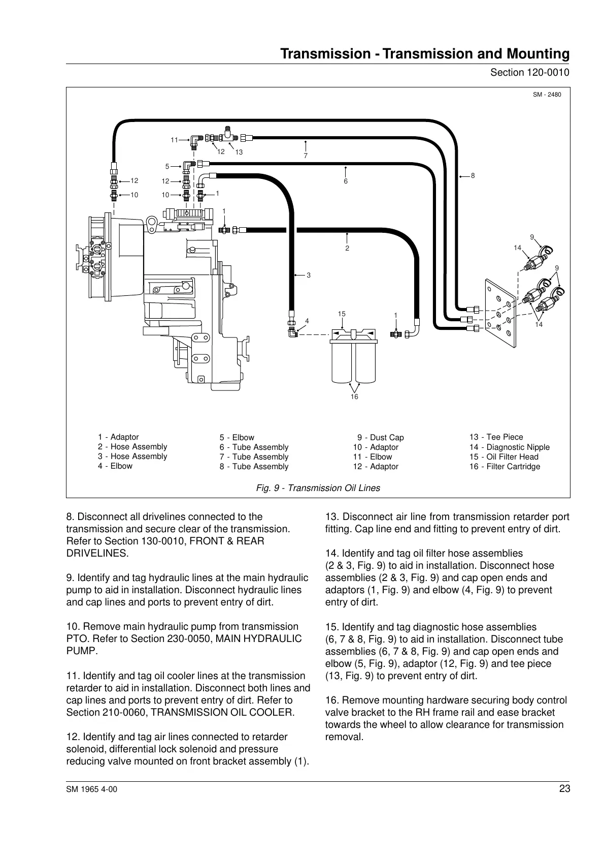
14. Identify and tag oil filter hose assemblies
(2 & 3, Fig. 9) to aid in installation. Disconnect hose
assemblies (2 & 3, Fig. 9) and cap open ends and
adaptors (1, Fig. 9) and elbow (4, Fig. 9) to prevent
entry of dirt.
15. Identify and tag diagnostic hose assemblies
(6, 7 & 8, Fig. 9) to aid in installation. Disconnect tube
assemblies (6, 7 & 8, Fig. 9) and cap open ends and
elbow (5, Fig. 9), adaptor (12, Fig. 9) and tee piece
(13, Fig. 9) to prevent entry of dirt.
16. Remove mounting hardware securing body control
valve bracket to the RH frame rail and ease bracket
towards the wheel to allow clearance for transmission
removal.
8. Disconnect all drivelines connected to the
transmission and secure clear of the transmission.
Refer to Section 130-0010, FRONT & REAR
DRIVELINES.
9. Identify and tag hydraulic lines at the main hydraulic
pump to aid in installation. Disconnect hydraulic lines
and cap lines and ports to prevent entry of dirt.
10. Remove main hydraulic pump from transmission
PTO. Refer to Section 230-0050, MAIN HYDRAULIC
PUMP.
11. Identify and tag oil cooler lines at the transmission
retarder to aid in installation. Disconnect both lines and
cap lines and ports to prevent entry of dirt. Refer to
Section 210-0060, TRANSMISSION OIL COOLER.
12. Identify and tag air lines connected to retarder
solenoid, differential lock solenoid and pressure
reducing valve mounted on front bracket assembly (1).
Transmission - Transmission and Mounting
1 - Adaptor
2 - Hose Assembly
3 - Hose Assembly
4 - Elbow
5 - Elbow
6 - Tube Assembly
7 - Tube Assembly
8 - Tube Assembly
9 - Dust Cap
10 - Adaptor
11 - Elbow
12 - Adaptor
13 - Tee Piece
14 - Diagnostic Nipple
15 - Oil Filter Head
16 - Filter Cartridge
Fig. 9 - Transmission Oil Lines
SM - 2480
9
9
14
14
1
15
16
7
6
2
3
4
1
1
8
12
10
12
5
10
11
12
13
Courtesy of Machine.Market
 Loading...


