Section 165-0020
SM 1629 1-99
1
SM - 248
BRAKE PARTS - Brake Parts - Front
DESCRIPTION AND OPERATION
WARNINGS
Use only hydraulic oils meeting specifications
outlined in Section 300-0020, LUBRICATION
SYSTEM. DO NOT use BRAKE FLUID (J1703).
Use of improper fluids is destructive to rubber
components of brakes resulting in loss of
braking and possible catastrophic failure.
Exercise extreme caution while working
on the braking system. The braking system
operates at high pressure.
When servicing wheel brake parts, do not
create dust by grinding or sanding brake pads
or wheel brake parts with a dry brush or
compressed air. A water dampened cloth
should be used for cleaning wheel brake parts.
The service brakes are of the calliper disc-type. The
calliper brake head is designed for use with hydraulic
oils meeting the specifications outlined in Section
300-0020, LUBRICATION SYSTEM. DO NOT USE
BRAKE FLUID (J1703).
The head is bolted to a mounting plate on the spindle.
The disc is bolted to the wheel. There are two brake
heads and a brake disc for each wheel.
Each calliper brake head assembly consists of a
torque plate, two brake pads; one on each side of the
disc and six brake pistons; three on each side of the
disc.
The brake is actuated by hydraulic oil entering the
brake head through one of the bleeder ports. The
piston bores on each side of the torque plate are
interconnected by internal passages.
When the brake is actuated, the hydraulic pressure
forces the pistons against the brake pads which are,
in turn, forced against each side of the brake disc,
slowing or stopping the disc and wheel rotation.
GENERAL INSPECTION
1. Inspect brake pads for wear. If the brake pad
friction material is worn down to 3 mm (0.12 in)
thickness, the pads must be replaced.
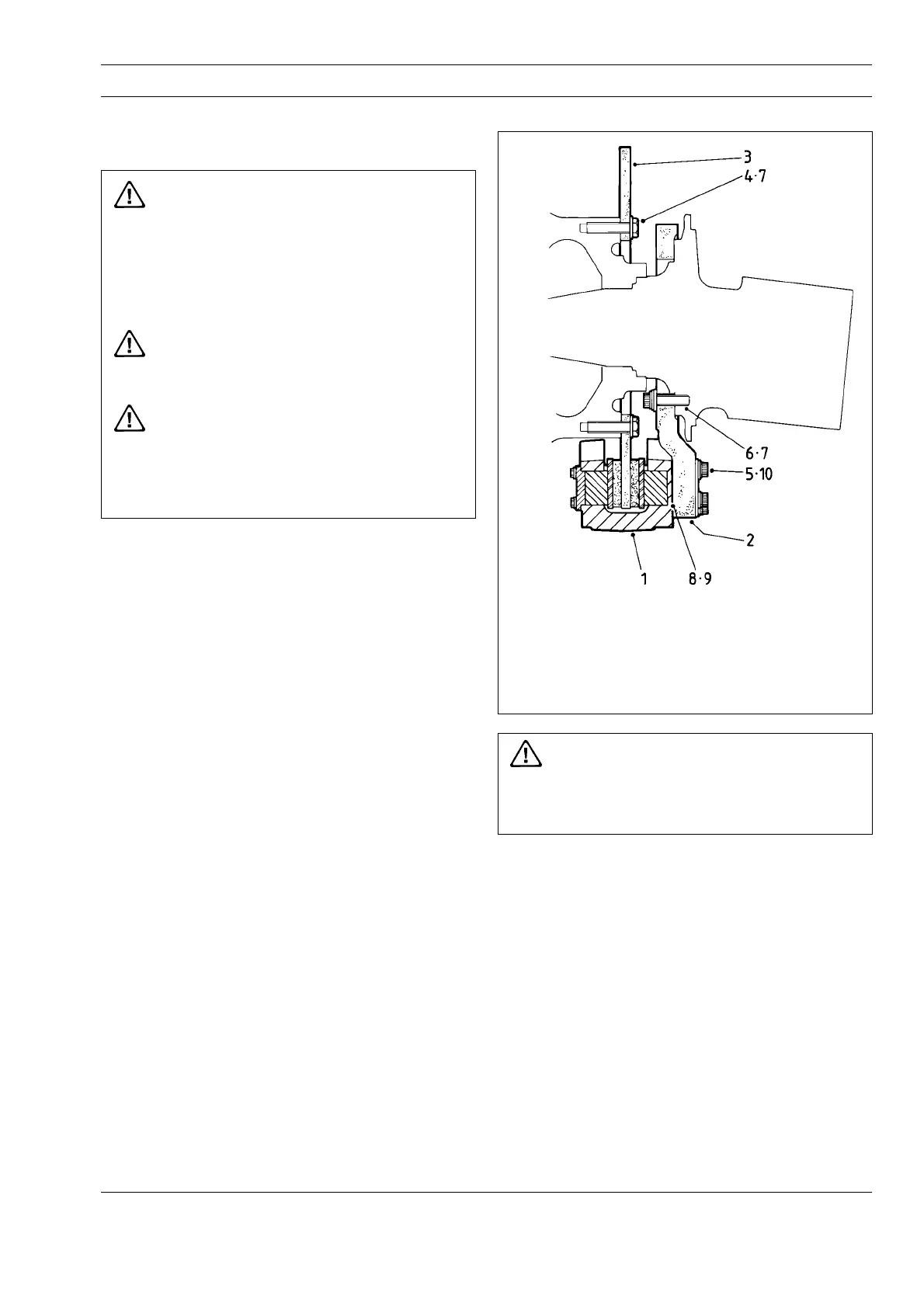
1 - Brake Head Assembly
2 - Front Carrier
3 - Brake Disc
4 - Bolt
5 - Capscrew
6 - Capscrew
7 - Washer
8 - Shim 1.53 mm (0.060 in)
9 - Shim 0.76 mm (0.030 in)
10 - Washer
Fig. 1 - Brake Head and Disc Mounting
WARNING
Failure to replace pads when worn to limits
will result in loss of braking and possible
catastrophic failure.
2. Inspect brake disc for wear. Measure thickness of
brake disc at three points on the brake pad friction
material contact circumference and determine the
average disc thickness.
Note: If the average disc thickness is 22 mm (0.88 in)
or less, the disc must be replaced. Refer to
Section 140-0040, WHEEL, RIM AND TYRE.
Disc Run Out
Maximum acceptable disc run out for disc speeds
lower than 100 rev/min is 0.762 mm (0.030 in) total
indicated reading (T.I.R.). Replace disc or repair hub
if necessary to correct this condition. Refer to
Section 140-0040, WHEEL, RIM AND TYRE.

 Loading...