Do you have a question about the TERMA SCANTER 6002 and is the answer not in the manual?
Outlines essential safety precautions and warnings for working with the radar system.
Specifies exposure limits and safety distances for electromagnetic fields according to standards.
Provides FCC compliance statements and warnings applicable to US installations.
Details ISED compliance statements and warnings for installations in Canada.
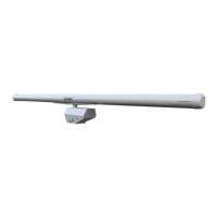
Describes the radar sensor system components: transceiver, antenna control unit, and antenna system.
Highlights the core technologies and features of the SCANTER 6002 radar system.
Explains how Doppler processing separates moving targets from clutter for improved detection.
Explains the system's architecture enabling software-defined features and flexibility.
Explains the benefits of Frequency Diversity (FD) and Time Diversity (TD) for target detection.
Describes the technique used to maximize detection range and improve resolution.
Covers techniques for improving target visibility in clutter using Doppler shifts.
Discusses techniques for improving surface target detection, considering smaller speed differences.
Explains how the system automatically adjusts to environmental conditions to maintain a flat noise floor.
Covers various methods for controlling and monitoring the radar system.
Methods for controlling the radar via its display, RST software, or IP network.
Details the BITE system for monitoring performance and diagnosing faults.
Defines the structure and content of BITE error and warning messages.
Indicates the operational state of transceiver components and entities.
Reports numerical measurements of parameters like noise figure and power levels.
Enables remote management and monitoring of the radar system.
Provides detailed status information on radar functions and system modules via RST.
Introduces the ET2 as a modern, knowledge-based tracker for various targets.
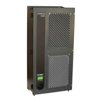
Lists and describes the main Line Replaceable Units (LRUs) within the transceiver.
Details the internal hardware layout and connections within the transceiver.
Provides an overview of the key modules comprising the transceiver system.
Details the SSPA modules, including description, reliability, and physical data.
Explains the function of the SSPA in amplifying the transmission signal to the required power level.
Details the RxTx module's role in frequency conversion and signal processing.
Outlines the primary tasks of the RxTx Control module in managing the radar system.
Describes the PC Controller Board, its components, and battery replacement.
Explains the CP4 board's function in signal processing using FPGAs.
Provides information on the PSU, its connections, and functions.
Illustrates the PSU's internal block schematic for power supply generation.
Covers the External I/O Board's role in handling radar communication and external interfaces.
Lists the various connections and functions available on the External I/O Board.
Lists the functionalities provided by the Radar Service Tool.
Provides an overview of maintenance activities, including preventive and corrective actions.
Details specific maintenance tasks for replacing components.
Lists and explains potential BITE errors and warnings encountered.