EasyManua.ls Logo

TERMA SCANTER 1002 - User Manual

Default Icon
62 pages
Print Icon
To Next Page IconTo Next Page
Loading...
1255194-HO Rev. A
SCANTER 1002 Radar System
User’s Manual
© Terma, Denmark. Proprietary and intellectual rights of Terma A/S and/or its subsidiaries are involved in the subject-matter of this material and all
manufacturing, reproduction, use, disclosure, and sales rights pertaining to such subject-matter are expressly reserved. This material is submitted for
a specific purpose as agreed in writing, and the recipient by accepting this material agrees that this material will not be used, copied, or reproduced in
whole or in part nor its contents (or any part thereof) revealed in any manner or to any third party, except own staff, to meet the purpose for which it was
submitted and subject to the terms of the written agreement.
This document is released for use only if signed by
relevant staff or stamped "EDM Release Controlled".
CM:
. .
..
TLM

Table of Contents

Question and Answer IconNeed help?

Do you have a question about the TERMA SCANTER 1002 and is the answer not in the manual?

Summary

Chapter 1: Introduction

Safety Instructions

Essential safety guidelines for operating and maintaining the radar system.

Chapter 2: SCANTER 1002 Radar System Overview

System Components

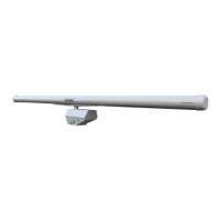
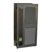
Details the main assemblies and modules comprising the SCANTER 1002 radar system.

Product Features

Lists the key technologies, capabilities, and specifications of the SCANTER 1002 radar.

Chapter 3: Functional Description

Software-Defined Functionality

Explains the radar's adaptable software architecture for flexible operation and feature integration.

Radar Control and Operation

Covers remote control, operational profiles, and built-in test equipment for system management.

Chapter 4: Hardware Interface

X1, Mains Power

Details the main power input connection for the transceiver.

X2, Aux Interface

Describes the auxiliary interface used for debugging and IP reset.

X3, LAN Network

Explains the Ethernet interface for system control and data communication.

GND Connection

Specifies the ground stud connection for protective earth.

Chapter 5: Radar Service Tool (RST)

Installation and Setup

Guides users through system requirements, installation, and initial setup of the RST.

RST Features and Operation

Covers RST functionalities like screen layout, preferences, and radar control operations.

Chapter 6: Software Installation and Maintenance

Resetting IP Address

Provides a procedure for resetting the transceiver's IP address to its default configuration.

Replacing Transceiver Software

Outlines the steps for performing a Device Firmware Update (DFU) on the transceiver.

Chapter 7: BITE Errors and Warnings

Chapter 8: Technical Terms and Definitions

Chapter 9: Abbreviations and Acronyms

Chapter 10: Annex A - Acknowledgement

TERMA SCANTER 1002 Specifications

General IconGeneral
CategoryRadar
ManufacturerTERMA
TypeSurface Surveillance Radar
Frequency BandX-band
RangeUp to 48 nautical miles
Antenna Rotation Speed24 or 48 rpm
Power Supply50/60 Hz

Related product manuals