Page 35/62
Rev. A
2017-12-04
SCANTER 1002 Radar System
User’s Manual
1255194-HO
5.6 Radar Control
When the Mains switch on the transceiver is turned to the Off position, the trans-
ceiver is in the “Off” state where it cannot function or be reached from remote.
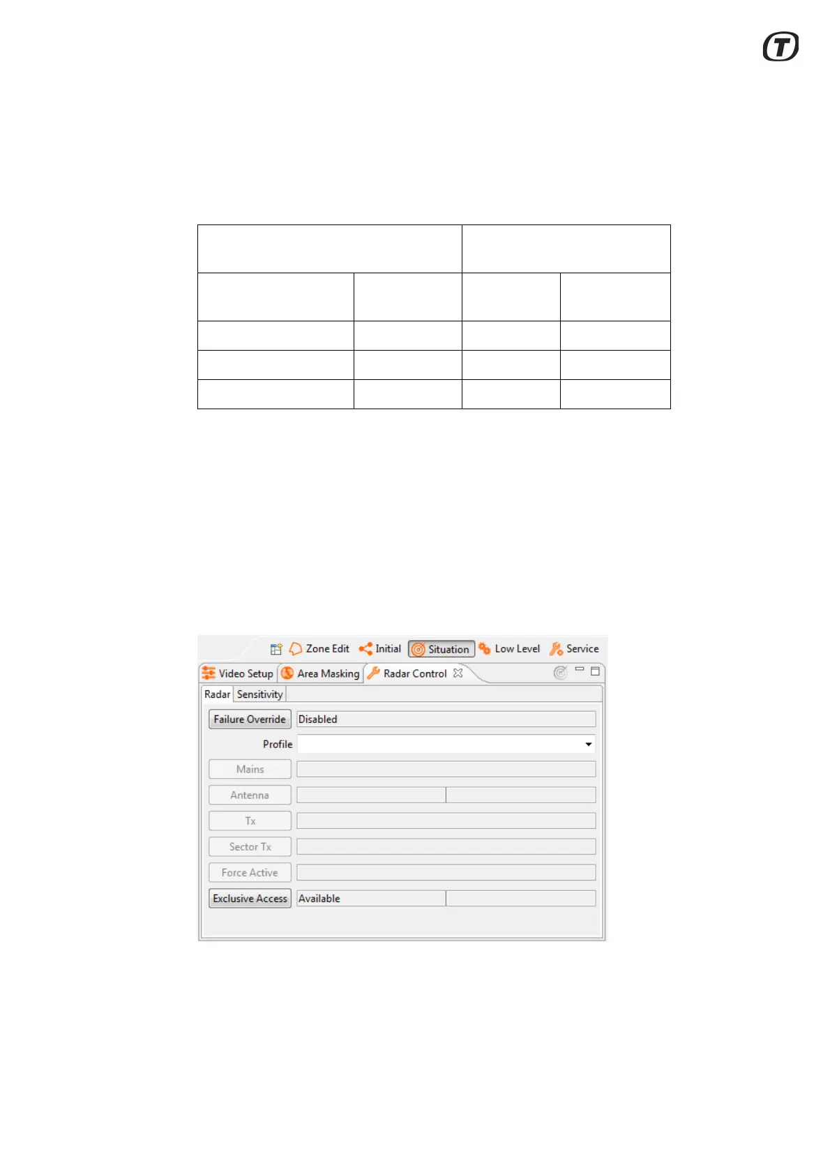
The transceiver can enter any of the states shown in the below table:
The “Standby” state is entered when the external mains switch is switched on and
the transceiver has performed a booting procedure that may last for 3-5 minutes.
The transceiver is checking the presence and condition of all hardware modules.
In this state, the LAN ports on the External I/O module are up and running. An RST
client can then connect to the transceiver through the LAN network.
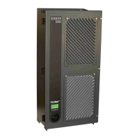
"Radar Control" view - Radar tab (Fig. 5.12 (p. 35)) is used for switching on/off the
antenna motor, the transmitter, and sector transmission.
Note that “Mains” cannot be switched off using the RST, but must be
switched off directly on the external switch.
Fig. 5.12 Radar Control view - Radar
To change transceiver configuration, the "Profile" drop down menu, see
Fig. 5.12 (p. 35), gives the possibility to select one of sixteen predefined profiles.
Radar Control view in the
Radar Service Tool
Transceiver states External
mains switch
Antenna Transmission
Off Off - -
Standby On Off Off
Fully functioning On On On