Page 43/62
Rev. A
2017-12-04
SCANTER 1002 Radar System
User’s Manual
1255194-HO
6 Software installation
6.1 Resetting IP address on transceiver to default (169.254.1.50)
This procedure should be performed if the connection to the transceiver cannot be
established. This may be the case if the transceiver has been replaced, or if the
transceiver is temporarily replaced with another transceiver, for instance in connec-
tion with service.
*
According to the CIDR notation, ‘/24’ means that netmask must be set to 255.255.255.0
(24 bit set, 8 bit not set).
Tool requirements: Screwdriver, flat
Spare parts / consumables: Reset Switch, X2 (902059-001) - part of toolkit
Service PC with Radar Service Tool (RST)
Network adapter
Est. time consumption 1/2 hour
1 Disconnect the external power cable on the transceiver.
2 Configure the network adapter on the service PC with an IP address on the
169.254.0.0/24* LAN segment.
3 Connect the network adapter on the service PC directly to the LAN con-
nector (X3) on the transceiver.
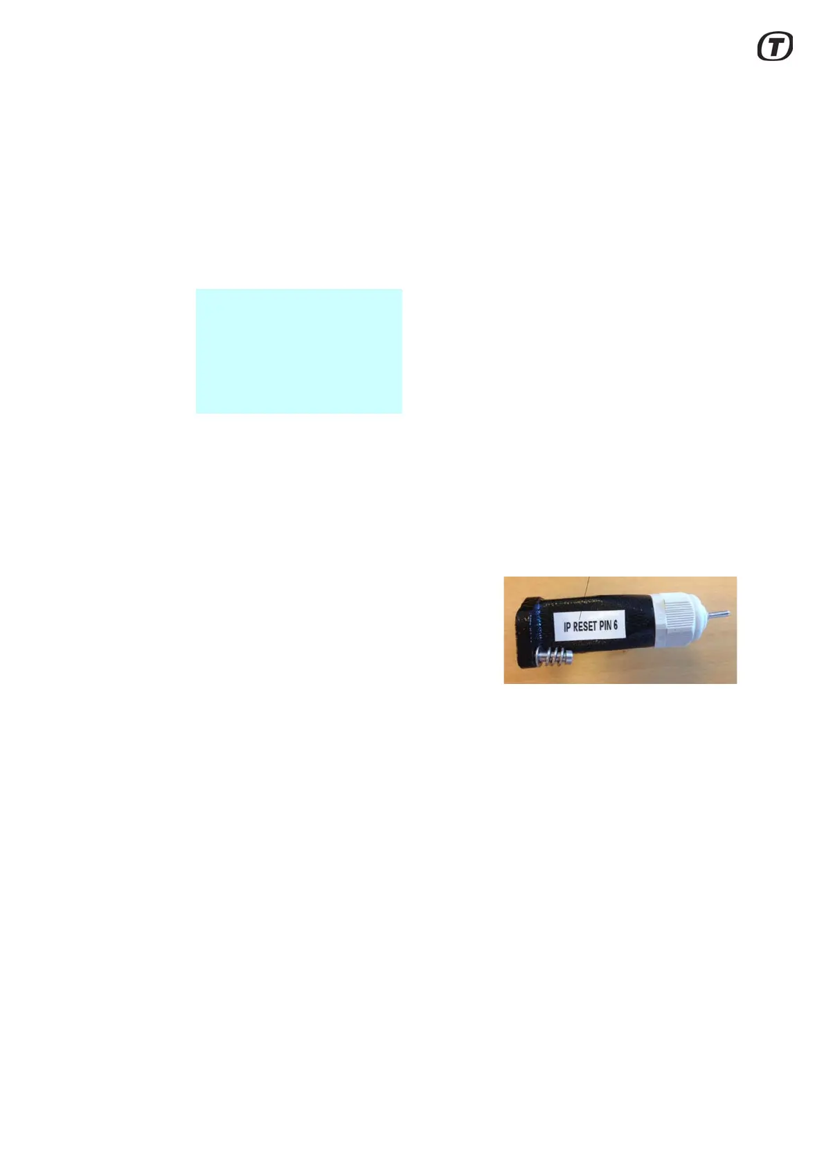
4 Connect the Reset Switch, X2 (see
Fig. 6.1 (p. 43)) to the Aux connec-
tor (X2) on the transceiver and fas-
ten the screws.
Fig. 6.1 Reset switch, X2 in IP
reset mode
5 Toggle the switch on the Reset
Switch, X2 to ”IP Reset” mode.
6 Connect the external power cable to the transceiver.
7 Wait for the bootloader to finish booting to “IP Reset” mode, as indicated
by the LED.
8 Toggle the switch on the Reset Switch, X2 to neutral position (middle).
9 In the RST “Parameters” view > Service and Installation\ Network Config-
uration, set “IP Address” to the final IP address for the transceiver on the
site in question. Also change “Default Gateway” and “Subnet Mask”
accordingly.
10 Set “Store Network Configuration” to ‘Store’ for changes to take effect.
 Loading...