Page 24/62
Rev. A
2017-12-04
SCANTER 1002 Radar System
User’s Manual
1255194-HO
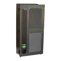
4.1 X1, Mains
Mains is supplied through the bottom plate and is the supply input for all modules
in the transceiver.
4.2 X2, Aux
The AUX interface is used for debugging by Terma personnel. It includes an IP
reset feature that may be applicable for end users. For details on IP reset, refer to
section 6.1 (p. 43).
4.3 X3, LAN
The LAN interface is used for control of the radar and for track output.
Description Data or Settings
Mains input 90-264 VAC
Frequency 47 - 63 Hz
Current 1A
Fuse 3.15AT
Connector Harting: Bulkhead type 09 40 703 0301 with 5
poles connector insert type 09 12 005 3001
Terminal Function Terminal Function
1 Phase 1 4 Neutral
2NC 5NC
3NC PEEarth
Terminal Function Terminal Function
1 GND 5 Reserved
2 RS-232-Adm PC_TX 6 IP Reset
3 RS-232-Adm PC_RX 7 DFU
4 Reserved 8 NC
Description Data or Settings
Interface standard Ethernet standard IEEE 802.3 10/100 BASE-T
Connector
Harting: Bulkhead type 09 40 703 0301 with
RJ45 insert type 09 45 200 1560
 Loading...