Page 44/62
Rev. A
2017-12-04
SCANTER 1002 Radar System
User’s Manual
1255194-HO
6.2 Replacing transceiver software
This procedure describes how to perform a Device Firmware Update (DFU). The
procedure should be performed if the transceiver PC Module has been replaced or
following an unsuccessful transceiver software update due to e.g. power failure.
Note: The procedure will erase all existing software on the transceiver.
*
According to the CIDR notation, ‘/24’ means that netmask must be set to 255.255.255.0
(24 bit set, 8 bit not set).
Tool requirements: Screwdriver, flat
Spare parts / consumables: Reset Switch, X2 (902059-001) - part of toolkit
Service PC with Radar Service Tool (RST)
Network adapter
Est. time consumption 1/2 hour
1 Disconnect the external power cable on the transceiver.
2 Configure the network adapter on the service PC with an IP address on the
169.254.0.0/24* LAN segment.
3 Connect the network adapter on the service PC directly to the LAN con-
nector (X3) on the transceiver.
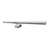
4 Connect the Reset Switch, X2 (see
Fig. 6.2 (p. 44)) to the Aux connec-
tor (X2) on the transceiver and fas-
ten the screws.
Fig. 6.2 Reset switch, X2 in DFU
mode
5 Toggle the switch on the Reset
Switch, X2 to “DFU” mode.
6 Connect the external power cable to the transceiver.
7 Wait for the bootloader to finish booting to “DFU” mode, as indicated by the
LED.
8 Toggle the switch on the Reset Switch, X2 to neutral position (middle).
9 Use the Radar Service Tool to upload transceiver core software (902085-
NF) to 169.254.1.50.
10 The transceiver will automatically reboot into the newly installed software.