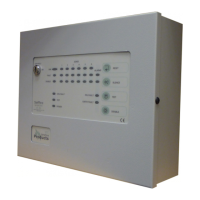
The Terofire Plus is a range of microprocessor-controlled fire alarm control panels designed to meet the requirements of BS5839 Parts 1 & 4 1988. The range includes panels with 2, 4, 6, 8, and 12 sense zones (detector zones). The Terofire 12 model is equipped with 4 alarm zones (bell zones), while other panels in the range feature 2 alarm zones.
Function Description:
The primary function of the Terofire Plus panel is to detect fire conditions and activate alarms. When a fire is detected by a device on a sense zone, the alarm zone devices automatically activate, and the specific zone that detected the fire is indicated on the front panel. The panel also allows for manual activation of alarms.
Key Features:
- Microprocessor Controlled: Ensures reliable and efficient operation.
- Zone Configuration: Available with 2, 4, 6, 8, or 12 sense zones and 2 or 4 alarm zones depending on the model.
- One-Man Test Facility: Simplifies testing procedures, allowing a single person to test zones.
- Class Change Input: Allows for remote activation of alarms.
- Fault Output: Provides an output signal in case of a fault.
- Volt-Free Changeover Contacts: Two sets of contacts that operate upon fire detection, useful for interfacing with other systems.
- Detector Head Removal Support: The system is designed to show a fault if a detector head is removed, while ensuring that call points remain functional. This requires specific base types (zener clamp or schottky diode) and appropriate end-of-line devices.
- Non-Latching Zone Configuration: Allows specific zones to automatically reset once the signalling device is cleared, without operating auxiliary contacts. This is particularly useful for interlinking fire alarm panels.
Installation Procedure:
Installation should be performed by qualified service personnel in accordance with IEE regulations and statutory requirements.
- Mounting: Use the metal box as a template to mark and drill fixing holes, then screw the panel to the wall. Ensure the panel is free from debris.
- Initial Power-Up (without field devices):
- Fit all end-of-line resistors in the panel.
- Connect the panel to an exclusive 240V AC fused supply.
- Switch on the mains supply; the internal buzzer will sound.
- Connect two sealed lead-acid batteries in series to provide a 24V DC supply.
- The panel should then be silent and in normal operating mode (power lamp on, alarms & buzzer silent). If a fault is indicated, refer to the fault-finding section.
- Connecting Sense Zones:
- Disconnect batteries and switch off mains.
- Remove the 3k3 end-of-line resistor from sense zone 1.
- Terminate sense zone 1 circuit wiring in the panel, observing correct polarity, and fit the end-of-line resistor at the extreme end of the circuit.
- Check all detectors and call points for correct wiring.
- Reconnect mains and battery supplies. If a fault is indicated, refer to fault finding.
- Repeat this procedure for additional sense zones and then alarm zones, adding them one at a time to simplify fault finding.
- Caution: Do not megger cables connected to the panel or field devices. Ensure no bare wires contact circuit boards.
Panel Operation:
- Enabling Buttons: Turn the key switch (top left) 90° to the ON position.
- Lamp Test: In normal condition, pressing the Reset button performs a lamp test.
- Resetting After Fire: Press Silence, then Reset.
- General Reset: Press Reset to return to normal condition from any activated function.
- Silencing Alarms: If fire is detected, alarms activate automatically. Press Silence to silence alarms; the internal buzzer continues until Reset is pressed.
- Silencing Internal Buzzer: If a fault is detected, the internal buzzer sounds. Press Silence to silence it; it will bleep every 25 seconds. A CPU Fault cannot be silenced.
- Manual Alarm Activation: Press Evacuate to sound alarms. Press Reset to silence them.
- One-Man Test:
- Press Test once; Zone 1 fault lamp flashes.
- Press Silence to put Zone 1 into test mode.
- Press Test again to cycle to Zone 2; Zone 2 fault lamp flashes, and if Zone 1 was in test mode, its fault lamp lights.
- The Test button cycles through zones, and Silence places the selected zone in test mode.
- Test lamp lights when a zone is in test mode.
- In test mode, a fire condition rings alarms for ~3 seconds before resetting; auxiliary contacts do not operate.
- If left in test mode without events for ~10 minutes, the panel returns to normal operation.
- If fire is detected on a non-test zone, the panel enters fire condition and exits test mode.
- Press Reset to exit test mode.
- Setting Non-Latching Zones:
- Press and hold the Test button.
- Momentarily press CPU RESET (SW1) inside the panel, wait a few seconds, then release Test.
- If the internal buzzer sounds continuously and CPU fault lamp is lit, press W/D RESET (SW2).
- Zone 1 fault lamp flashes. Press Test to cycle through zones.
- Press Silence to configure the selected zone as non-latching.
- Wait ~25 seconds for the panel to return to normal operation.
- This setting is retained as long as power is connected; re-enter if power is completely removed.
Fault Finding:
- Front panel buttons not working: Turn key switch to ON.
- Fault lamp & zone fault lamp flashing, internal buzzer sounding (Sense Zone Faults):
- Open/short circuits on sense zone wiring, detector head removal.
- Check detectors, call points, wiring (as per diagrams), 3k3 resistor or active end-of-line device (with capacitor at terminals if active EOL).
- Fault lamp flashing, power lamp lit, internal buzzer sounding (Alarm Zone Faults):
- Open/short circuits on alarm zone wiring, blown alarm fuses, blown 28V auxiliary supply fuse.
- Check/replace fuses (with identical parts), alarm zone wiring (as per diagrams), 10k end-of-line resistor.
- Fault lamp flashing, power lamp off, internal buzzer sounding (Power Supply Faults):
- Blown battery fuse, battery supply not present, damaged/uncharged batteries, blown mains fuse, mains supply not present.
- Check/replace fuses, ensure correct battery connection and secure leads. If new batteries, they may need charging.
- CPU Fault lamp lit, internal buzzer sounding:
- Processor stopped. Press CPU RESET (SW1) then W/D RESET (SW2) on the main circuit board.
- Panel does not indicate fire when call point/detector tested:
- Faulty device or wiring. Check device firing resistance (510 ± 200 ohms) and 3k3 resistor or active end-of-line device.
- Head removal not working:
- Incorrect base or wiring. Use zener clamp base with 3k3 EOL or schottky diode base with active EOL (capacitor at sense zone terminals if active EOL).
Technical Specifications (Terofire 2 / Terofire 4 / Terofire 6 / Terofire 8 / Terofire 12):
- Mains Voltage (V AC): 240 (all models)
- System Voltage (V DC): 28.4 (all models)
- Quiescent Current (mA): 63 / 84 / 108 / 108 / 110
- Quiescent Current, Unsilenced Fault (mA): 75 / 96 / 120 / 120 / 148
- Minimum Battery Size (Ah) - 2 x 12V Required: 2.1 / 2.8 / 6.0 / 6.0 / 9.0
- Detector Voltage (V DC): 24 (all models)
- Number of Sense Zones: 2 / 4 / 6 / 8 / 12
- Maximum Number of Detectors per Zone: 20 (all models)
- Firing Resistance (Ohms): 510 ± 200 (all models)
- Sense Zone End of Line (Ohms): 3k3 (all models)
- Alarm Voltage (V DC): 28.4 (all models)
- Number of Alarm Zones: 2 / 2 / 2 / 2 / 4
- Maximum Alarm Current per Zone (mA): 250 / 500 / 500 / 500 / 500
- Maximum Number of Sounders per Zone: 10 / 20 / 20 / 20 / 20
- Alarm Zone End of Line (Ohms): 10k (all models)
- Maximum Auxiliary Supply Current (mA): 125 (all models)
- Panel Weight Including Batteries (kg): 5 / 6.5 / 7.5 / 7.5 / 12
- Panel Dimensions (mm): 270 x 230 x 85 (Terofire 2) / 330 x 290 x 80 (Terofire 4, 6, 8) / 390 x 320 x 110 (Terofire 12)
- Note: All calculations must account for startup current, especially for xenon beacons.
Wiring Diagrams:
- Sense Zone (3k3 EOL): For zones entirely comprised of call points.
- Sense Zone (Active EOL): Requires a 100uF capacitor fitted at the sense zone terminals inside the panel. Active EOL units are supplied separately.
- Alarm Zone: Requires a 10k end-of-line resistor at the end of the circuit. Motorised fire bells can be used, but solenoid bells MUST NOT be connected.
- Relay to Alarm Zone: A relay (24V DC coil) can be connected anywhere on the alarm zone wiring, with two 1N4001 (or equivalent) diodes.
- Relay to Auxiliary Fault (AF) Output: A fault relay (24V DC coil) can be connected, requiring a 1N4001 (or equivalent) diode.
- Ringing Alarms Remotely (Class Change): Connecting the CC terminal to the 28V Aux - terminal will sound the alarms.
- Signalling Fire to Another Panel: Connect auxiliary contacts of Panel B to a sense zone of Panel A via a 510R resistor and 3k3/Active EOL. If Panel A's zone is non-latching, it will reset automatically when Panel B's contacts open.
- Connecting Magnetic Door Holders: Auxiliary contacts can switch door holders. When the panel goes into fire, power to the door holders is removed, allowing doors to close.
Maintenance:
- A Terofire System Log Book is provided for recording all events, including fire alarms (real or false), faults, tests, temporary disconnections, and engineer visits with notes on work carried out and outstanding.
- Regular checks of fuses, wiring, and battery connections are essential for fault resolution.